
Choosing a flexible FPC connector for compact electronics starts with matching pitch, pin count, and contact rating to the flex circuit layout, then confirming actuator style, plating, and assembly access in the finished housing. The right FPC interface supports reliable signal or power transfer without forcing awkward cable routing or fragile hand-soldering steps. In many compact products the FPC connector sits beside board-to-board or I/O interconnects, so selection should consider the full interconnect map—not only the flex-to-board joint.
Match Pitch, Pin Count, And Flex Layout
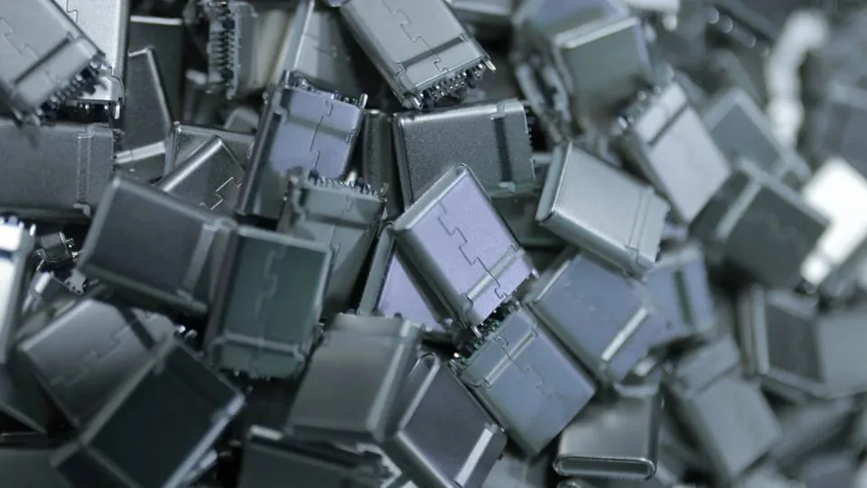
Begin with the flexible printed circuit geometry. Record track density, keep-out zones near folds, and the mating direction relative to the stiffener. Pitch and position count must fit the FPC pad pattern without crowding solder fillets or ZIF/LIF actuator clearance. Over-dense pitch on a thin flex often creates yield loss during first insertion even when electrical ratings look adequate on paper.
When the same module also uses mezzanine stacking, review nearby board-to-board options early so mechanical envelopes do not collide. Ultra-compact consumer stacks frequently combine an FPC display or camera link with 0.4 mm pitch board-to-board connectors for consumer electronics. Catalog orientation for those BTB families (per catalog) lists mated heights 1.5–4.0 mm, pin counts 30–70, 0.3 A per contact, and an operating range of −40 to 125°C—useful when you need a parallel rigid-board path beside the flex.
Electrical Needs: Signal, Power, And Integrity
List whether the FPC carries low-speed control, camera or display differential pairs, or local power. Confirm contact current, insulation expectations, and whether the path needs controlled impedance or dedicated grounds. Derate for temperature and for grouped power pins. If a nearby rigid interface carries higher current, keep budgets separate rather than assuming the FPC contact can absorb overflow.
For display differential links that leave the board as a cable rather than a bare flex, compare LVDS connectors in the same design review. Mixed programs fail when FPC actuator height is frozen while LVDS locking clearance is still open. Treat catalog high-speed listings on adjacent BTB families (for example high-speed claims on listed 0.4 mm themes, pending validation) as orientation for those rigid interfaces only—never as a substitute for validating the FPC path itself.
Actuator Style, Mechanical Access, And Durability
FPC connectors differ by actuator type (front flip, back flip, slider), contact side (top or bottom), and whether the design is ZIF or low-insertion-force. Choose based on how operators or fixtures will seat the flex in production and whether field service is expected. Measure insertion and withdrawal feel on samples, and confirm terminal retention after the planned number of open/close cycles for your product.
Mechanical reliability also depends on housing support. Thin devices that open for battery or camera service put cyclic stress on the FPC joint. Vibration in modules designed for automotive applications may favor locking cable connectors or floating board-to-board mates for the rigid stack while the FPC remains a short internal jump—see floating board-to-board connectors when residual board misalignment is a risk. Catalog floating examples (per catalog) include CBB020 at 80 pins / 4.75 mm mated height and CBB023/024/025 20-pin hybrids with 3.0 A power pins; confirm float capability in design review without treating informal travel numbers as specifications.
Materials, Plating, And Process Compatibility
Copper-alloy contacts with tin or gold plating and heat-resistant housings are typical building blocks. What matters for procurement is that plating callouts and housing grades match the approved revision. Review solderability notes for SMT FPC receptacles, stencil apertures, and reflow profile limits with process engineering before releasing Gerbers. Avoid improvising hand touch-up on fine FPC contacts when automated placement is the intended process.
Packaging and ESD/moisture control protect fine terminals before placement. Factory process and inspection context is summarized on the manufacturing quality page. Upstream document readiness—outline, mating, and land pattern—is covered in what technical drawings and test data matter most before connector procurement.
Compact-Device Application Checklist
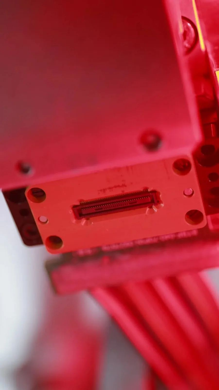
| Check item | Why it matters | Practical action |
|---|---|---|
| Pitch & pin count | Density vs flex pad yield | Match controlled FPC drawing |
| Actuator / contact side | Assembly access & service | Fixture trial on samples |
| Current & signal plan | Power / SI budget | Separate FPC vs BTB budgets |
| Height & keep-outs | Housing clash | CAD clash with shields/batteries |
| Nearby interconnects | Stack & EMI | Review BTB / LVDS / USB keep-outs |
| Plating revision | Contact life | Lock PN + plating on PO |
Typical compact applications that combine FPC with dense BTB include watches, earphones, glasses, phones, tablets, and notebooks (per catalog application themes for listed 0.4 mm BTB families). If USB I/O shares the board, keep USB Type-C connectors on a separate line item so RFQs do not mix flex actuator notes with Type-C shell requirements.
Sample And Approval Discipline
Request samples against a revision-controlled drawing, not a photo. Inspect actuator feel, seating flushness, and solder fillets on representative coupons. Use the inspection mindset in what buyers should check before approving connector samples, then gate mass release with how to approve connector samples for mass production. Fine-pitch handling risks that also apply near FPC pads are summarized in common risks when sourcing fine-pitch or miniature connectors.
FAQ
How do I choose between top-contact and bottom-contact FPC connectors?
Choose based on flex fold direction and stiffener orientation so the copper lands face the contacts without an extra twist that stresses the polyimide.
Can I use a board-to-board connector instead of an FPC connector?
Sometimes for short rigid stacks. FPC remains better for hinged, folded, or out-of-plane routing. Compare both envelopes in CAD before freezing copper.
What current rating should I assume from a catalog family?
Do not assume. Confirm the exact PN datasheet. Nearby 0.4 mm BTB signal contacts are commonly listed at 0.3 A per catalog; that value does not automatically apply to the FPC series under review.
When should LVDS connectors enter the same review as FPC?
When the display or camera path leaves as a differential cable assembly rather than a bare flex soldered or ZIF-mated to the board.
What belongs in the first FPC RFQ?
Pitch, pin count, contact side, actuator type, plating preference, application environment, annual volume band, and controlled drawings or competitor PNs.
Request A Quote
Share FPC pitch and pin count, actuator style, application notes, and any parallel BTB or LVDS interfaces on the same module. Weicheng can help map compact interconnect needs and supply drawings or samples for engineering review. Start an RFQ at https://www.wcjmconnect.com/contact.