

USB Type-C
Type-C receptacle and interface options for compact electronics.
Browse subseries
Connector portfolio
Filter by family, pitch, stack height and contacts. Confirm the exact variant with engineering.
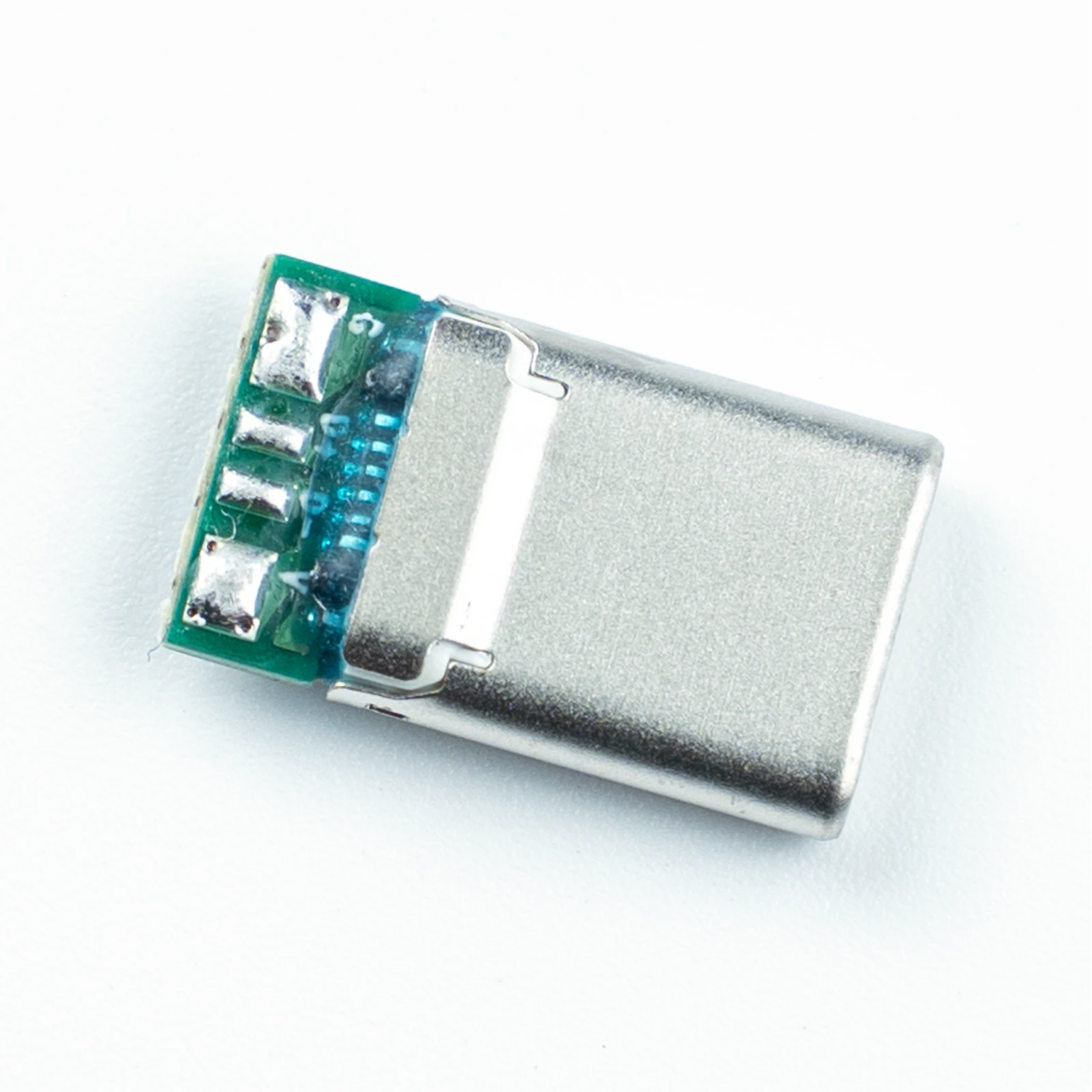
CUB005-1202G-01
- Pitch
- 0.5 mm
- Contacts
- 12 pin
- Mated height
- Pending
- Termination
- Straddle mount
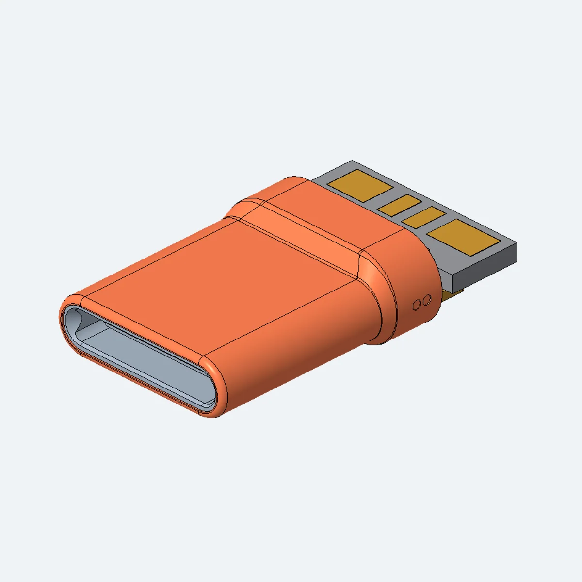
CUB008-1202G-01
- Pitch
- 0.5 mm
- Contacts
- 12 pin
- Mated height
- Pending
- Termination
- Straddle mount
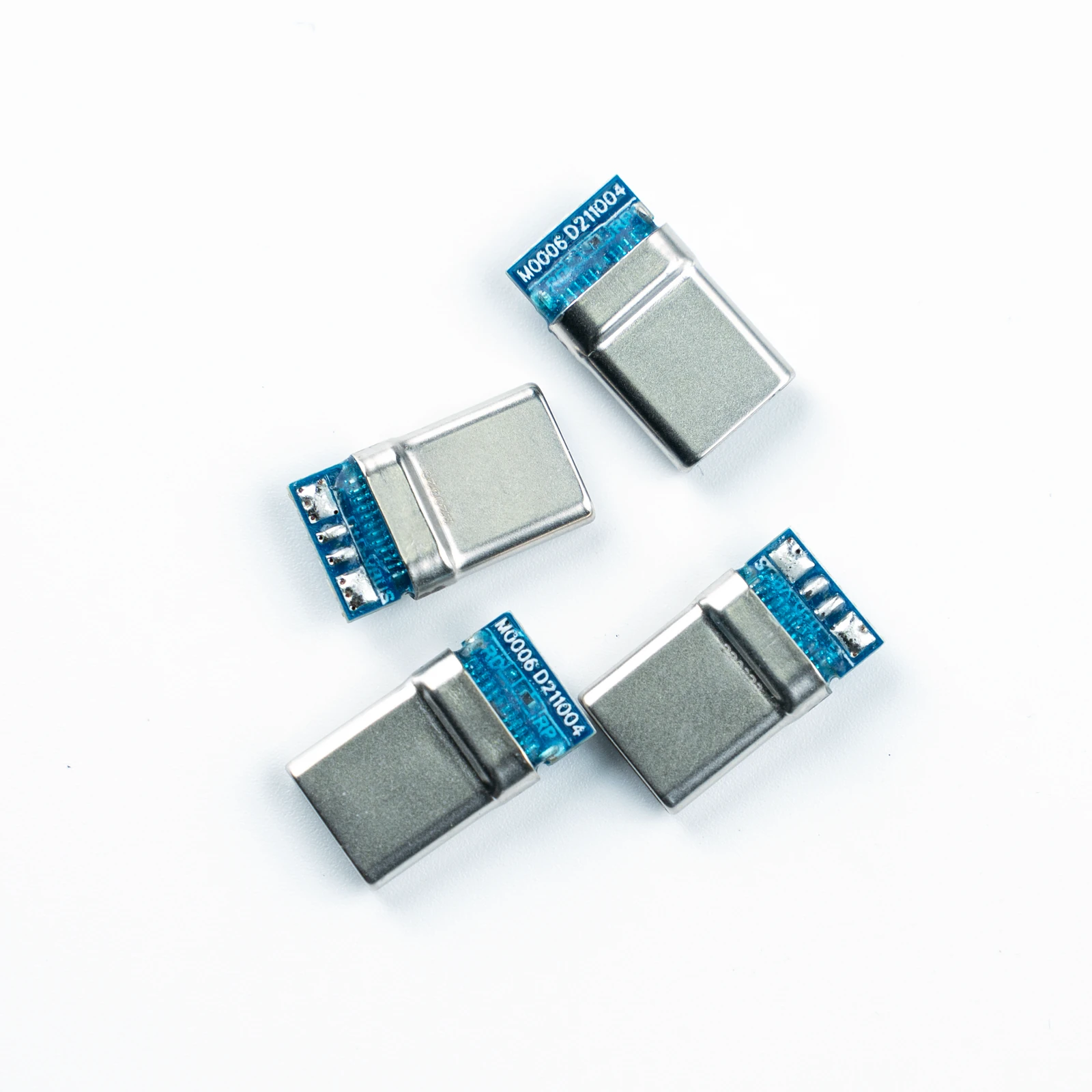
CUB006-2202G-A1
- Pitch
- 0.5 mm
- Contacts
- 22 pin
- Mated height
- Pending
- Termination
- Straddle mount
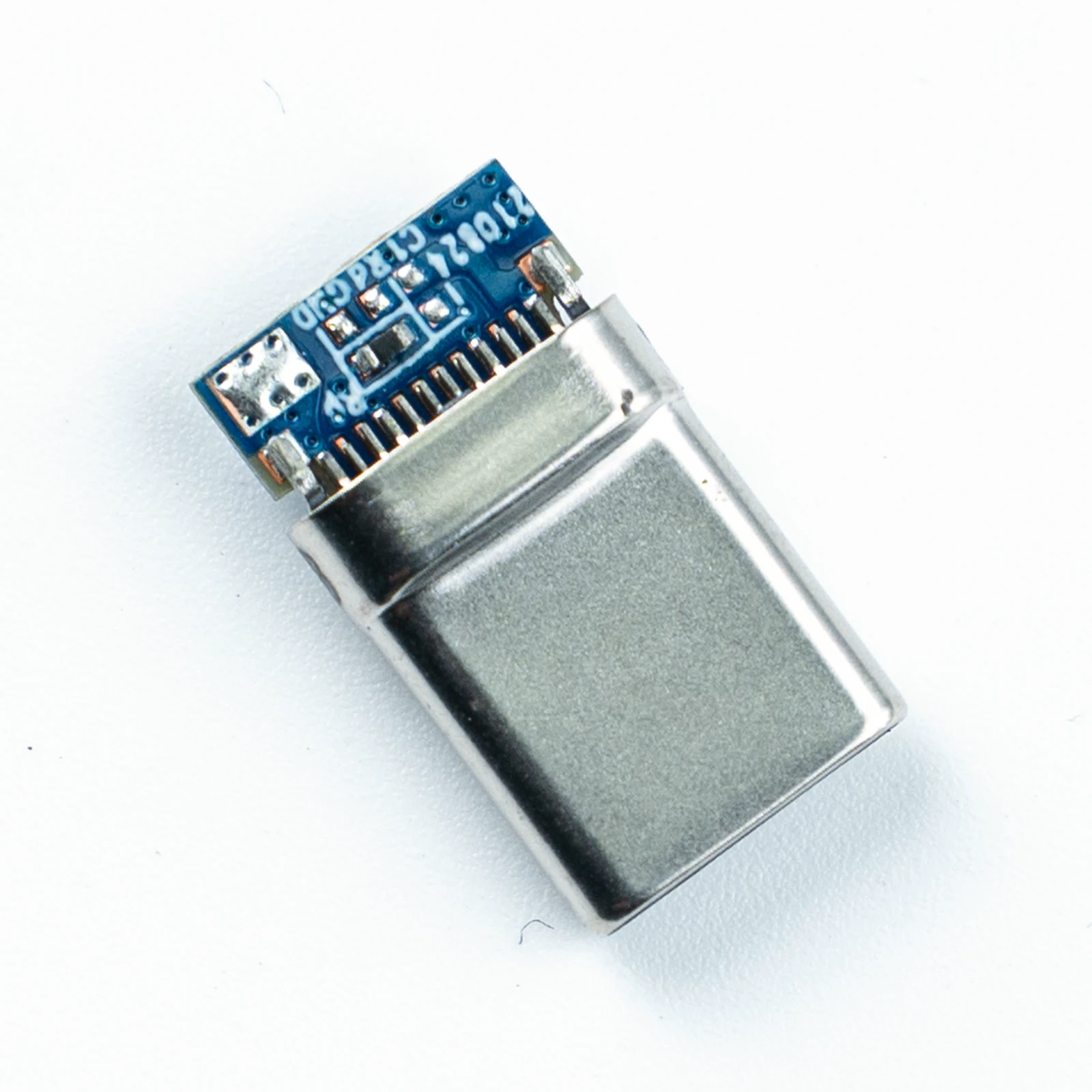
CUB009-2202H-01
- Pitch
- 0.5 mm
- Contacts
- 22 pin
- Mated height
- Pending
- Termination
- Straddle mount
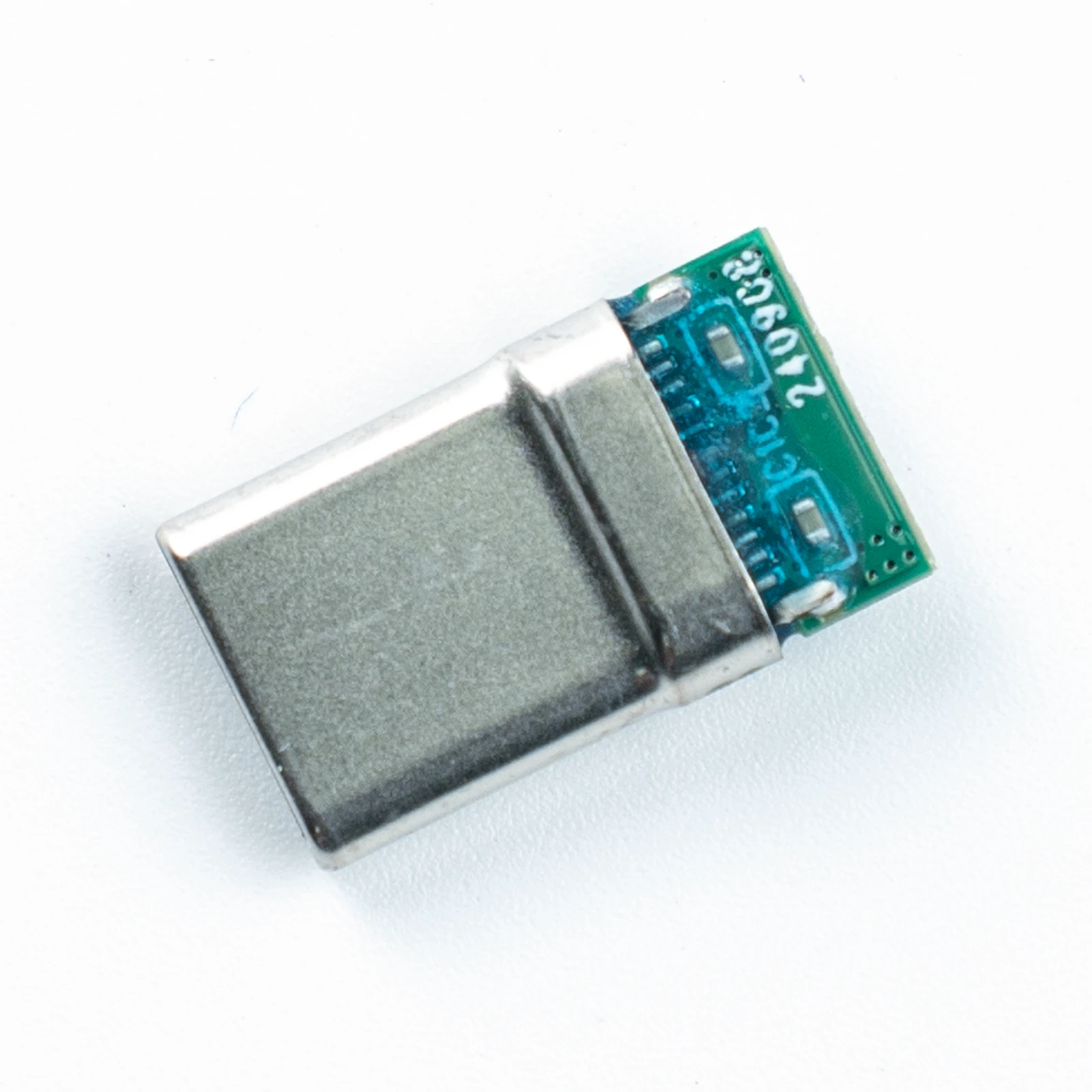
CUB017-2202F-01
- Pitch
- 0.5 mm
- Contacts
- 22 pin
- Mated height
- Pending
- Termination
- Straddle mount
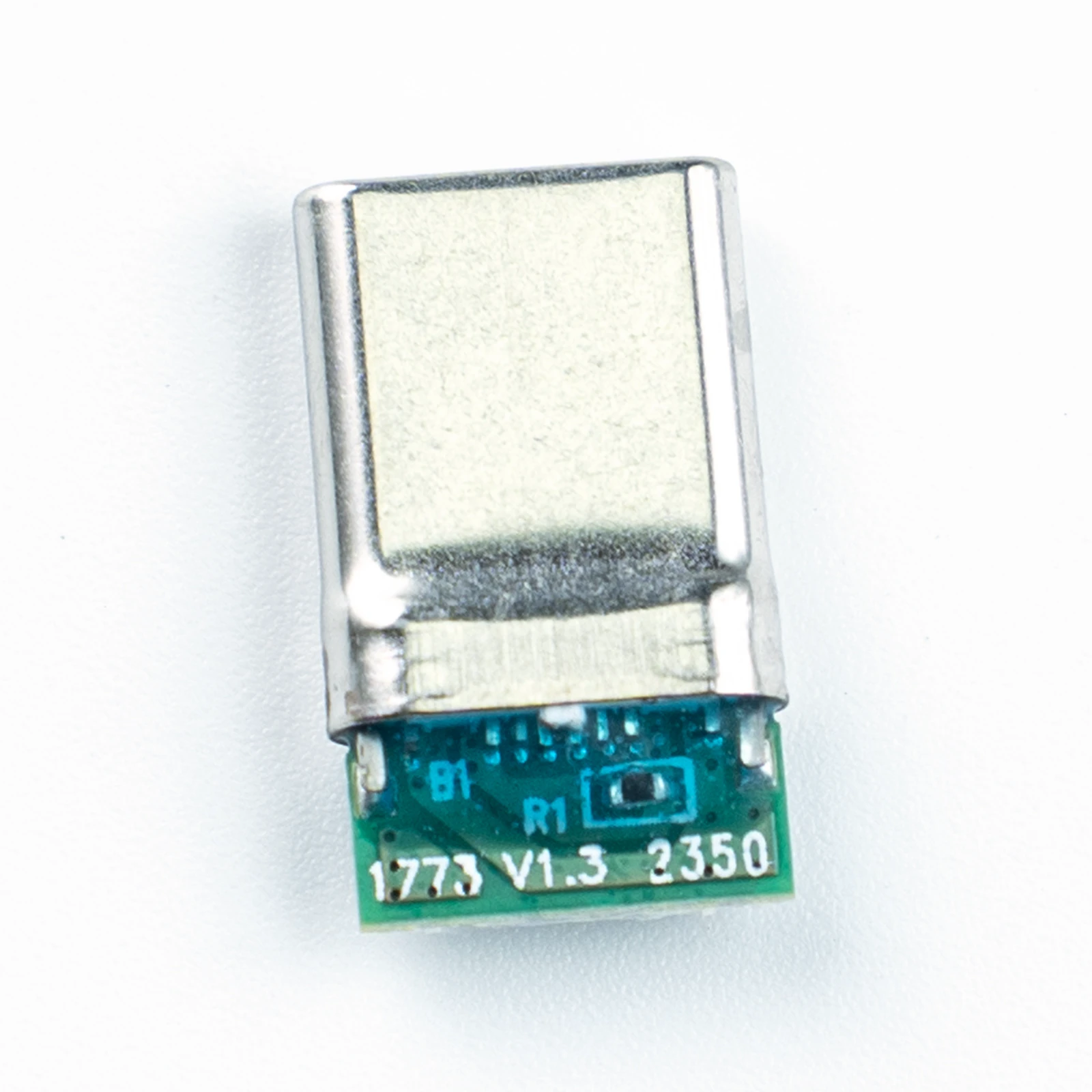
CUB022-1202G-01
- Pitch
- 0.5 mm
- Contacts
- 12 pin
- Mated height
- Pending
- Termination
- Straddle mount
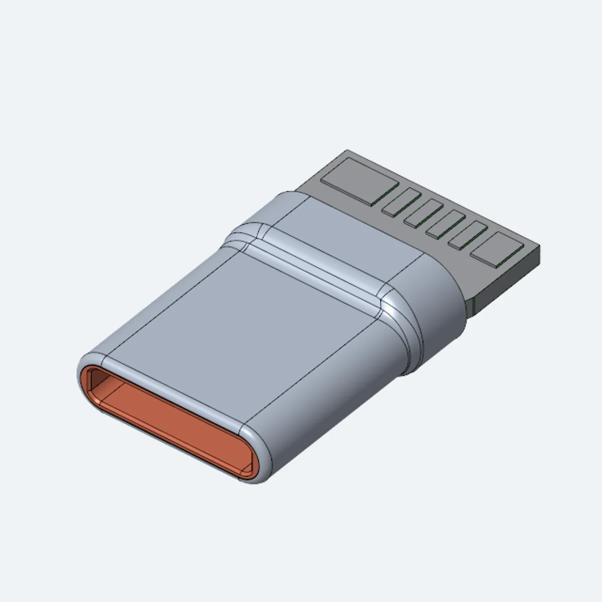
CUB086-1202G-0A
- Pitch
- 0.5 mm
- Contacts
- 12 pin
- Mated height
- Pending
- Termination
- Straddle mount
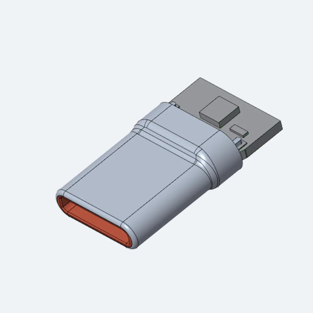
CUB086-1202G-XA
- Pitch
- 0.5 mm
- Contacts
- 12 pin
- Mated height
- Pending
- Termination
- Straddle mount
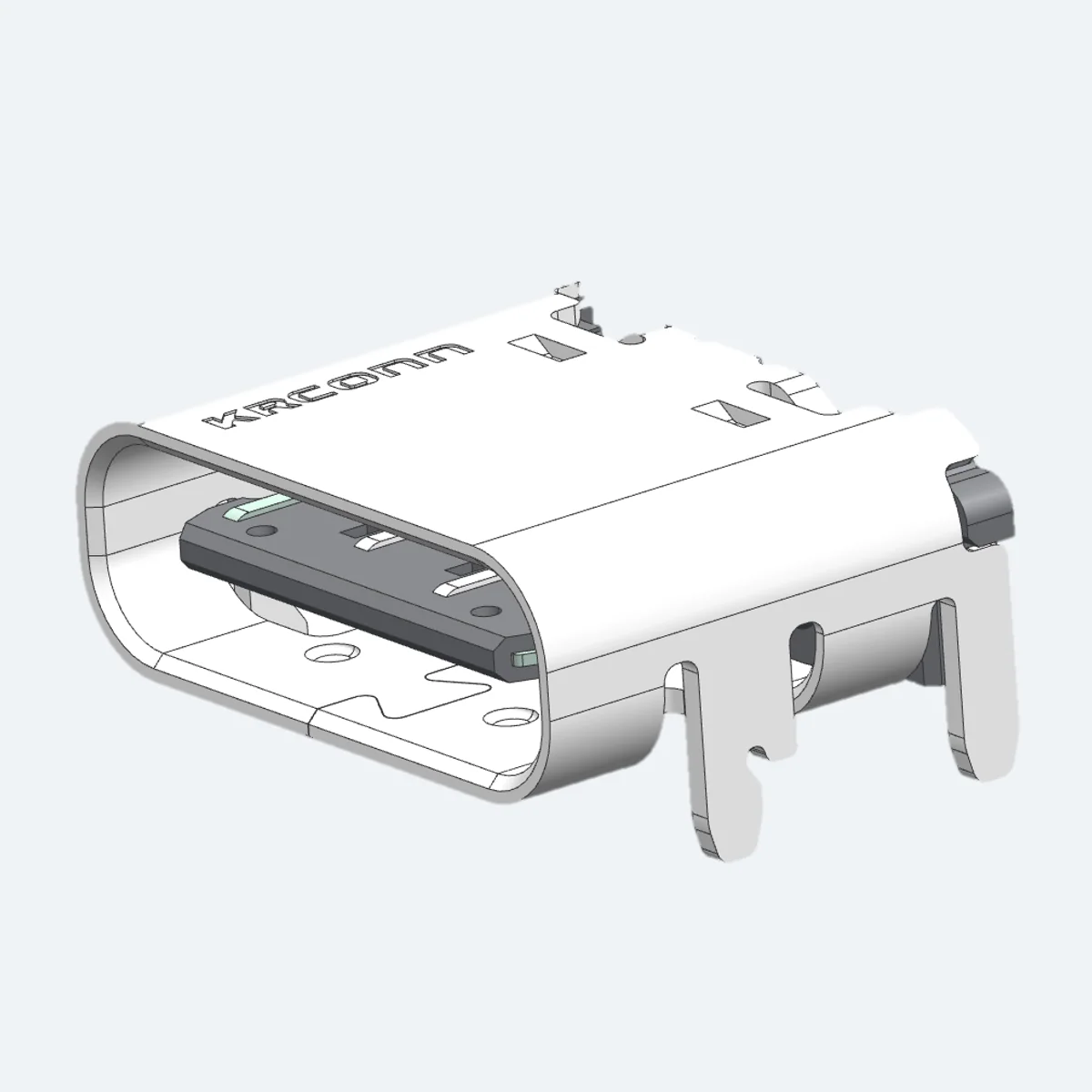
CUB004-**S1A-01
- Pitch
- 0.5 mm
- Contacts
- 16 pin
- Mated height
- Pending
- Termination
- Pending
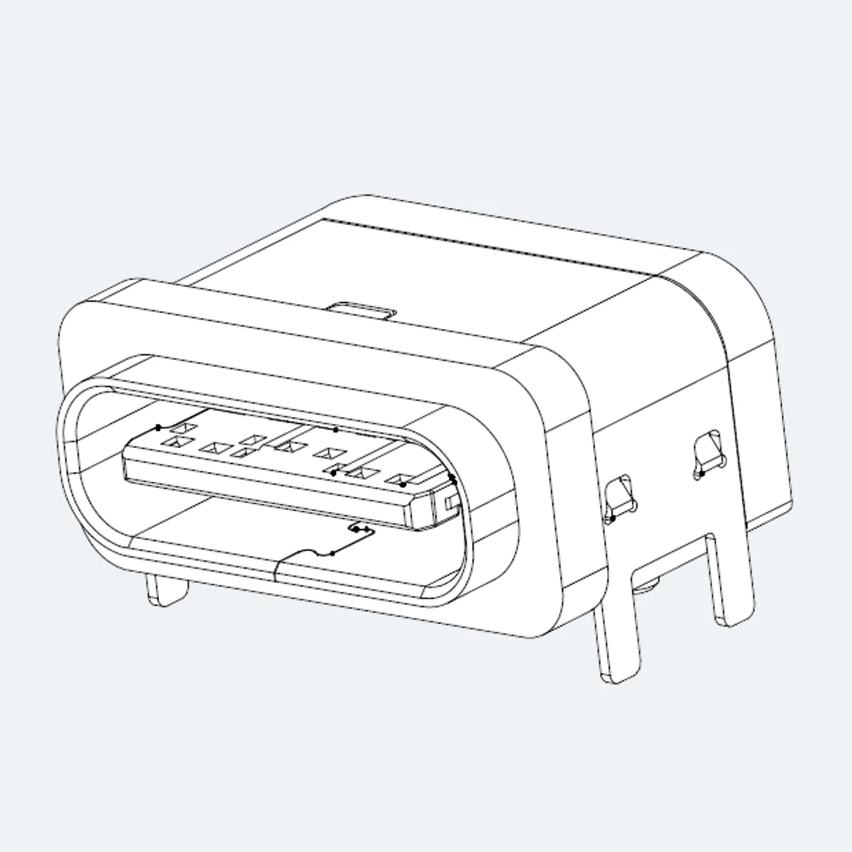
CUB014-0060H-01
- Pitch
- 1.2 mm
- Contacts
- 6 pin
- Mated height
- Pending
- Termination
- Pending
No products match those filters. Try another pitch, height or pin count.
Selecting a USB Type-C connector
The factory product catalog lists 10 USB Type-C model records. Across those records, pitch is 0.5–1.2 mm; mated height is not stated in the sourced records; and contact count is 6–22 contacts. These are ranges observed in the listed variants, not a substitute for a controlled drawing of the exact order code.
A Type-C receptacle sits at the boundary between the product enclosure and the PCB. Port position, board thickness, shell retention and assembly access must be considered before the footprint is committed.
Begin by drawing the two surfaces that must be joined. Record the board outline, location of each connector, approach direction and space available for a mating operation. If a cable or harness is involved, include its exit path and bend allowance. This basic sketch exposes conflicts that a list of nominal electrical values cannot show. The connector should be evaluated as part of the complete assembly, rather than as an isolated component photograph.
Compare the factory catalog variants for geometry, mounting style, contact arrangement and available drawings. Define the electrical functions needed by the device separately; the connector does not determine a system protocol on its own.
Next, fix the actual contact assignment. Record signal, ground and power positions, and note any contacts that need a separate current review. Compare the pin count listed for the exact catalog record with the circuit plan. A higher count can increase routing and board-space demands, while a lower count may leave no room for future revisions. A selection table is useful for narrowing candidates, but it does not replace a pin assignment or a released drawing.
Compare sourced catalog records
The records below are generated from the current factory product data. A value marked Pending confirmation has not been accepted as a verified part-level specification. Select the linked model to see its drawings, mating notes and the source attached to each available value. If a project depends on a tolerance, current rating or environmental result, request the controlled file and identify the specific test condition.
| Model | Pitch | Contacts | Mated height | Termination |
|---|---|---|---|---|
| CUB005-1202G-01 | 0.5 mm | 12 pin | Pending | Straddle mount |
| CUB008-1202G-01 | 0.5 mm | 12 pin | Pending | Straddle mount |
| CUB006-2202G-A1 | 0.5 mm | 22 pin | Pending | Straddle mount |
| CUB009-2202H-01 | 0.5 mm | 22 pin | Pending | Straddle mount |
| CUB017-2202F-01 | 0.5 mm | 22 pin | Pending | Straddle mount |
| CUB022-1202G-01 | 0.5 mm | 12 pin | Pending | Straddle mount |
| CUB086-1202G-0A | 0.5 mm | 12 pin | Pending | Straddle mount |
| CUB086-1202G-XA | 0.5 mm | 12 pin | Pending | Straddle mount |
| CUB004-**S1A-01 | 0.5 mm | 16 pin | Pending | Pending |
| CUB014-0060H-01 | 1.2 mm | 6 pin | Pending | Pending |
The comparison table links to all 10 model records across 10 base series names. Where two models share a base series, their suffixes may still identify a different contact count, gender, height or geometry. The exact order code should travel with every drawing request, quotation draft and engineering note.
Mechanical and electrical review
Check the recommended PCB land pattern against the board stack and placement tolerances. Keep assembly tooling, inspection access and any enclosure interference in view. Review connector retention and the intended mating sequence before freezing the mechanical design. For an electrical review, use the model-level current and voltage values only where the catalog or controlled specification actually states them. Assess signal performance in the finished board or cable channel rather than treating a connector family name as proof of system performance.
Confirm the exact receptacle variant and mechanical drawing. Any claim about data rate, charging behavior or environmental sealing requires evidence for the complete design and should not be inferred from appearance.
Document the remaining questions before requesting samples. A useful engineering inquiry includes the candidate model, board layout, target mated height, contact assignment, expected quantity, project stage and the tests required by the destination product. Ask for the latest datasheet revision and a matching two-dimensional or three-dimensional drawing when available. If any value on this page differs from a newly released controlled document, the current document should govern the design review.
Common questions
How should I begin selecting a USB Type-C connector?
Start with the assembly drawing, required connection type, available space and exact contact assignment. Compare catalog values, then request the current controlled part drawing.
Does the same pitch prove two parts will mate?
No. Pitch is only one dimension. The mating interface, order code, orientation and stack height must all be confirmed.
Where can I check mated height and contact count?
Use the sourced product table as an initial filter. Check the controlled drawing for the exact ordering variant before PCB release.
Are all catalog values valid for every variant in a family?
Not necessarily. A series value may not cover each ordering suffix. Fields without variant-level confirmation are identified separately.
How do I request a drawing or sample for review?
Add the exact part number and target quantity to the RFQ workspace, then export the draft for your own review and sending.