
Preventing common connector field failures depends on validation that maps electrical, mechanical, and environmental tests to real use—not on a single “looks OK” sample photo. Most returns trace to incomplete stress coverage, plating or dimensional drift between sample and volume, or process mismatch after release. Build a validation plan that ties drawings, sample inspection, and pilot evidence before customer builds commit.
Map Failure Modes Before Choosing Tests
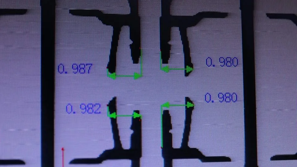
List the failures that matter for your product: intermittent contact, high contact resistance, cracked solder joints, housing crack, bent terminals, moisture-driven leakage, or EMI upset. Each mode points to a test family. Contact resistance and insulation resistance cover many electrical intermittents. Insertion/withdrawal force and terminal retention cover handling damage. Vibration, shock, and thermal cycling cover solder and fretting risks. Humidity or corrosion-related tests apply when the enclosure is not sealed.
Do not copy a generic lab menu. Programs designed for automotive applications often need deeper vibration and temperature mapping than a sealed consumer wearable, while ultra-compact phones and tablets emphasize fine-pitch coplanarity and mating yield. Catalog orientation for dense consumer BTB (per catalog) lists 0.4 mm families with mated heights 1.5–4.0 mm, 30–70 pins, 0.3 A, and −40 to 125°C—use those as PN shortlist hints, then validate the exact part against your stress profile.
Electrical Validation That Predicts Field Behavior
Verify contact resistance (initial and after defined mating cycles if serviceable), insulation resistance, dielectric withstand where the program requires it, continuity against the pin map, and functional or signal-integrity sampling for differential paths. Derate current for temperature and grouped pins. Listed 0.5 mm BTB signal contacts commonly show 0.5 A per contact per catalog; hybrid floating themes with 3.0 A power pins (CBB023/024/025, per catalog) still need PN-level confirmation before you treat those values as design limits.
High-speed board mates and display links should include channel-aware checks. Review candidate series on 0.4 mm pitch board-to-board connectors for consumer electronics and LVDS connectors when those interfaces sit on the critical path. Treat catalog high-speed listings (for example high-speed claims on listed 0.4 mm themes, pending validation) as orientation, then validate layout rules for your channel.
Mechanical And Environmental Validation
Measure insertion and withdrawal feel with gauges when possible. Confirm latch engagement, seating flushness, and terminal scrape. For screwed assemblies or vibration-heavy modules, compare rigid mates with floating board-to-board connectors. Catalog floating examples (per catalog) include CBB020 80 pin at 4.75 mm mated height; confirm float capability in design review without inventing travel millimeter claims.
Run environmental evidence that matches the enclosure and mounting: thermal cycling or shock, humidity, and vibration/shock profiles defined by the product team. Document sample conditioning and sample size. A pass stamp without method notes is weak protection when a second plating lot arrives.
Sample Approval Versus Process Validation
Inspection answers whether a sample conforms. Field reliability also needs process gates: first article on production-intent parts and a pilot on the real SMT or harness line. Use what buyers should check before approving connector samples for dimensional, mating, soldering, and electrical checks, then how to approve connector samples for mass production for sign-off, pilot, and change control. Drawing and report discipline that feeds every gate is covered in what technical drawings and test data matter most before connector procurement.
Fine-pitch dimensional and handling risks that become field intermittents are summarized in common risks when sourcing fine-pitch or miniature connectors. Factory inspection context sits on manufacturing quality. For wider process windows on multi-board stacks, compare 0.5 mm pitch automotive board-to-board connectors (heights 3.0–5.0 mm, 10–80 pins, 0.5 A per contact per catalog) when space allows.
Validation Coverage Table
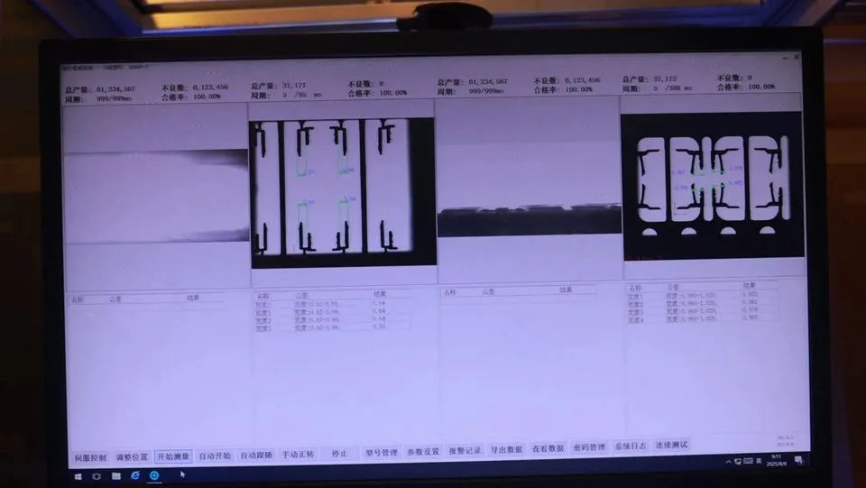
| Risk in field | Validation focus | Evidence to retain |
|---|---|---|
| Intermittent signal | CR stability, plating revision | CR logs + plating callout |
| Open after reflow | Coplanarity, stencil, reflow | Coupon photos + AOI notes |
| Hard mate / bent pins | Force, keying, packaging | Mating records + pack photos |
| Solder crack / fretting | Vibration + float decision | Profile + design-review note |
| Moisture leakage | Humidity / IR checks | Method + lot ID |
| Wrong pin map | Continuity vs drawing | Signed pin-map check |
Practical Validation Checklist
[ ] Failure modes listed against product stress
[ ] PN, revision, and plating locked to samples
[ ] Electrical tests defined before powering boards
[ ] Mechanical force / latch checks recorded
[ ] Environmental scope matched to enclosure
[ ] Production-intent first article planned
[ ] Pilot yield and mating metrics agreed
[ ] Change-control path named for plating/tooling
Close The Loop From Lab Evidence To Line Evidence
Lab reports alone do not prevent field returns if the production line uses a different stencil, reflow profile, or mating fixture than the sample build. After electrical and environmental evidence exists, run a controlled pilot that measures first-pass SMT yield and final mating yield under production conditions. Capture AOI images and force-gauge notes in the same approved-part record as the lab summaries so later lots are judged against one baseline.
When a dual source is introduced, repeat the critical electrical and mating checks on that source even if the pitch and pin count match on paper. Look-alike housings can differ in plating, coplanarity, or latch geometry enough to recreate the intermittents you thought validation had closed. Keep retained samples from each accepted lot so incoming quality can compare appearance and seating height without relying on memory.
FAQ
Is a datasheet “pass” enough to prevent field failures?
No. Datasheets summarize. You need method-tied results for the stresses your product sees, plus process validation on the line that will ship.
Should every program run full environmental suites on every sample lot?
No. Map tests to risk. Use sample electrical/mechanical inspection for disposition, and schedule environmental depth according to program criticality.
How do floating connectors change validation?
Add intentional offset trials and solder-joint stress review. Floating absorbs residual misalignment; it does not remove the need for footprint control.
What often causes sample-OK then field fail?
Silent plating or packaging changes, skipped pilot, or dual-sourcing look-alike parts without drawing diffs.
Where do drawings fit in validation?
Controlled outline, mating, and PCB drawings define what you are validating. Without revision lock, test reports cannot be tied to the PO part.
Request A Quote
Share target PN or drawings, stress profile notes, and the validation gates you require (sample, first article, pilot). Weicheng can align documentation and sample classes for engineering review. Start at https://www.wcjmconnect.com/contact.