
When sourcing connectors for automotive applications on PCBs, prioritize stress-profile fit (temperature, vibration, sealing of the module), electrical ratings with derating, mechanical locking and float needs, and documentation depth your OEM program requires. Selection that stops at a familiar pitch often fails under vehicle vibration or thermal cycling. Treat these parts as designed for automotive applications only after evidence matches your customer’s written requirements—not after reading a category label.
Start From The Vehicle Stress Profile And Customer Specs
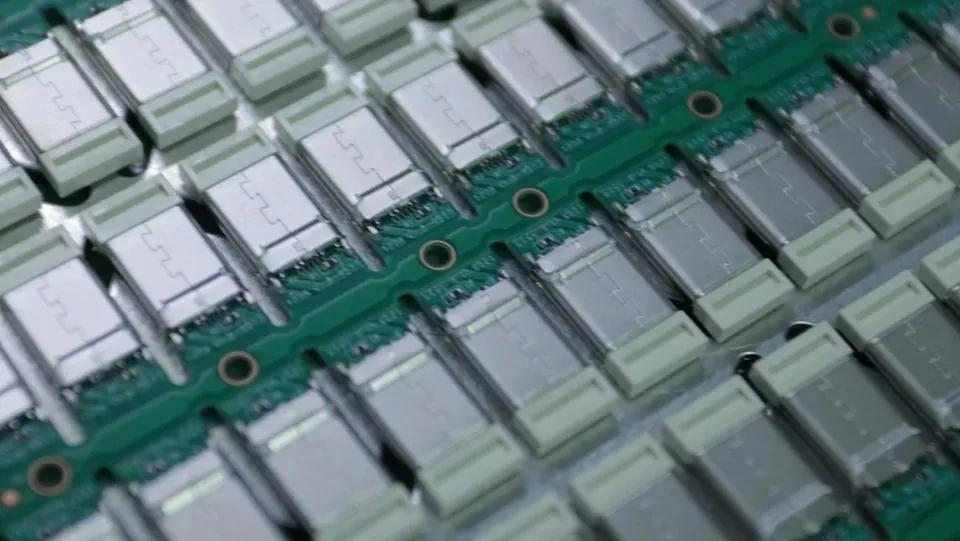
List operating temperature, vibration/shock expectations, humidity or chemical exposure, mating cycles (factory plus service), and whether the interface is inside a sealed module or near a connector panel. Ask which OEM document packs apply (for example customer PPAP-style or IMDS-style items) and verify evidence yourself. Do not assume a series meets a vehicle program until the documentation and test mapping are confirmed.
Compare rigid and floating board-to-board options early when boards are screwed into housings. Review 0.4 mm pitch automotive board-to-board connectors, 0.5 mm pitch automotive board-to-board connectors, and floating board-to-board connectors against the same checklist. Catalog orientation (per catalog): 0.4 mm BTB themes list heights 1.5–4.0 mm, 30–70 pins, 0.3 A, −40 to 125°C; 0.5 mm BTB lists heights 3.0–5.0 mm, 10–80 pins, 0.5 A per contact. Floating examples include CBB020 80 pin at 4.75 mm height and CBB023/024/025 20-pin hybrids with 3.0 A power pins and TC9-1000BASE listing per catalog—confirm float capability in design review without inventing travel millimeter values.
Electrical Performance For Module Interconnects
Verify contact current for signal and any power pins, insulation expectations, and whether differential or high-speed nets need controlled return paths. Derate for ambient temperature and grouped pins. Camera, radar, and domain-controller modules may combine dense BTB with Ethernet transition hardware—keep automotive high-speed Ethernet connectors on a separate RFQ line when T1 channels are in scope. Catalog Ethernet-related orientation (per catalog) for listed transition series includes COT001 (1.8/2.5 mm), COT002 (2.54 mm), COT022 (1.80/2.50 mm side entry), 5 A power pins, 0.35 mm float, TC9 1000BASE-T1 (STP), 10 mating cycles, −40 to 125°C, and 500 V withstanding—designed for automotive applications such as LiDAR and similar sensing modules; confirm the exact PN datasheet before layout freeze.
Display links inside the cabin may still use LVDS connectors; do not mix LVDS locking notes with Ethernet channel budgets in one vague line item.
Mechanical Strength, Vibration, And Mating Durability
Connectors designed for automotive applications must hold contact normal force and housing locks through vibration and thermal expansion. Evaluate insertion/withdrawal force, terminal retention, latch stability, and expected cycles across production, service, and rework. Floating contact structures help when PCB tolerance and screw stack-up would otherwise overload solder joints. Pitch choice also affects process window: denser 0.4 mm parts need stronger SMT discipline, while 0.5 mm often widens placement and mating margins when space allows—see 0.4 mm vs 0.5 mm pitch board-to-board connectors.
Materials, Plating, And Process Fit
Copper-alloy terminals with suitable plating and high-temperature housings are baseline building blocks. Lock plating callouts to the approved revision and confirm solderability under your reflow profile. Packaging (reel, tray, pick-up cap) must fit automotive electronics manufacturing lines. Factory process and inspection practices that buyers can audit against are summarized on manufacturing quality. Drawing and test-data packages that should precede tooling are covered in what technical drawings and test data matter most before connector procurement.
Supplier Documentation And Quality Evidence
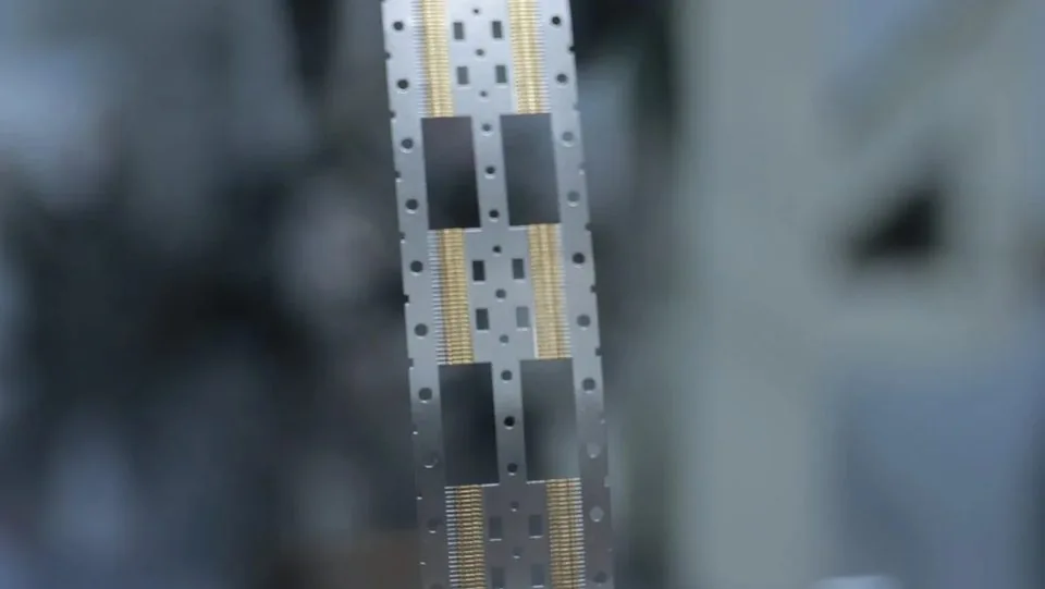
Select suppliers that can provide current quality-system documentation on request, stable process controls, and clear inspection records. Buyers should verify any certificates against the issuing body and confirm site scope. Request batch traceability and pre-shipment inspection evidence relevant to your program. Sample inspection and mass-production gates remain separate: use what buyers should check before approving connector samples and how to approve connector samples for mass production.
Sourcing Factors Table
| Factor | Why it matters | Buyer action |
|---|---|---|
| Stress profile | Vehicle environment | Write temp/vibration/seal notes |
| Pitch / height | Density vs yield | Lock CAD stack + process window |
| Current / SI | Module power & data | Derate; separate Ethernet/LVDS lines |
| Float / lock | Vibration & screw stack | Design-review decision recorded |
| Plating revision | Contact life | PN + plating on approved record |
| Documentation | OEM release | Verify declarations & reports |
Align Purchasing, Engineering, And Quality On One Record
Create a single approved-part record that lists manufacturer, full PN, drawing revision, plating note, packaging code, and the stress-profile summary used for release. Purchasing should order only against that record. Incoming inspection should copy the same critical dimensions and electrical sampling plan. Contract manufacturers building the same module in different plants need the same controlled package so local “helpful” footprint tweaks do not create intermittent opens that look like connector defects.
When annual volume bands or ramp curves change, update the record’s forecast notes so packaging and capacity conversations stay honest—without treating informal calendar promises as commitments. If Ethernet transition hardware or LVDS display links share the module, keep those PNs as linked but separate records so T1 channel evidence is not mixed with mezzanine BTB height approvals.
FAQ
What wording should RFQs use for vehicle programs?
Prefer “connectors designed for automotive applications” plus the stress profile and document pack you need. Avoid relying on informal category nicknames without evidence.
When should buyers choose floating BTB in a vehicle module?
When board misalignment, housing screws, or vibration would stress solder joints on a rigid mate. Floating helps residual movement; it does not replace footprint control.
How should Ethernet connectors be sourced relative to PCB BTB?
As a separate interface with its own channel and mechanical notes. Do not bury T1 requirements inside a generic BTB line item.
Are catalog current ratings enough for design freeze?
Treat 0.3 A / 0.5 A / 3.0 A / 5 A style listings as per-catalog orientation, then confirm the exact PN datasheet and derating rules.
What documents reduce sourcing risk most?
Controlled drawings, plating callouts, stress-mapped test summaries, and a verified certificate/declaration pack tied to the selling entity and site.
Request A Quote
Share stacking height, pitch preference, vibration/temperature notes, and documentation expectations for your program. Weicheng can map requirements to connectors designed for automotive applications and supply drawings or samples for review. Start at https://www.wcjmconnect.com/contact.