
Choose 0.4 mm pitch board-to-board connectors when board area is the binding constraint and your SMT process can hold a tighter window; choose 0.5 mm when you need a wider mating and placement window, broader pin-count flexibility, or higher per-contact current headroom. Neither pitch is universally better—the correct choice follows space, process capability, current budget, and mechanical stack. Use catalog parameters as orientation (per catalog), then lock the exact PN drawing before Gerber release.
What Pitch Changes In Practice
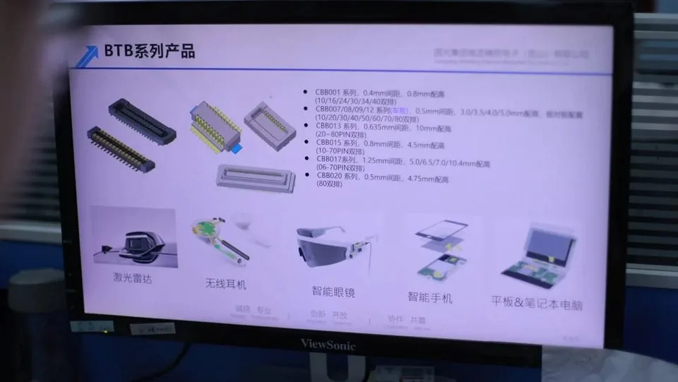
Pitch is the center-to-center distance between adjacent contacts. Moving from 0.5 mm to 0.4 mm increases contact density for the same connector length, which helps ultra-compact modules. The trade-off is a narrower alignment window during SMT placement and mating. High-volume lines with stable fixtures often run 0.4 mm successfully; manual assembly, large tolerance stacks, or screwed housings often favor 0.5 mm—sometimes with a floating structure.
Catalog Parameter Comparison (Per Catalog)
| Parameter | 0.4 mm BTB (CBB063/066/069 themes) | 0.5 mm BTB (CBB007 + receptacles) |
|---|---|---|
| Rated current (signal) | 0.3 A per contact (per catalog) | 0.5 A per contact (per catalog) |
| Mated height range | 1.5–4.0 mm (per catalog) | 3.0 / 3.5 / 4.0 / 5.0 mm (per catalog) |
| Pin-count range | 30–70 pins (CBB066 50–70) (per catalog) | 10–80 pins (per catalog) |
| Operating temperature (listed 0.4 families) | −40 to 125°C (per catalog) | Confirm PN datasheet |
| High-speed listing example | high-speed listing pending validation | Confirm PN datasheet |
| Typical applications | Smart watches, earphones, glasses, phones, tablets, notebooks (per catalog) | Multi-board / general BTB electronics (when specific catalog app lists are not stated) |
Product pages for side-by-side review: 0.4 mm pitch board-to-board connectors for consumer electronics, 0.4 mm pitch automotive board-to-board connectors, and 0.5 mm pitch automotive board-to-board connectors.
Density And Board Space
If the layout cannot close at 0.5 mm for the required pin count, 0.4 mm is often the deciding factor. Wearables and ultra-thin consumer stacks commonly land in this camp. If space is available, many experienced layout teams keep 0.5 mm to protect yield and serviceability. Density decisions should include ground and shield strategy for high-speed nets—not only raw pin count.
Process Window, Mating, And Yield
Smaller pitch tightens true-position and coplanarity needs. Bridging, opens, and bent terminals during first mate show up more readily on 0.4 mm when stencil design or handling is marginal. A 0.5 mm part generally forgives more PCB warpage and placement offset. When boards are screwed into a housing before mating, consider floating board-to-board connectors so residual misalignment stresses the float mechanism more than the solder joints. Catalog floating examples (per catalog): CBB020 80 pin at 4.75 mm mated height; CBB023/024/025 20 pin with 3.0 A power pins and TC9-1000BASE listing—confirm float capability in design review without treating informal travel numbers as specs.
Fine-pitch sourcing risks are expanded in common risks when sourcing fine-pitch or miniature connectors.
Electrical Capacity And Hybrid Power

Per catalog, listed 0.4 mm signal contacts are commonly 0.3 A, while listed 0.5 mm signal contacts are commonly 0.5 A. For signal-only interfaces the difference may be minor after derating; for local power it matters. Hybrid designs with dedicated power pins (for example 3.0 A power pins on listed floating hybrids, per catalog) let you keep dense signal pitches while feeding higher current safely. Always derate for temperature and grouped pins, and confirm the exact PN datasheet.
Application-Oriented Decision Guide
Space-critical consumer modules (watches, earphones, glasses, phones, tablets, notebooks) → start with 0.4 mm families and verify SMT capability.
Multi-board electronics needing wider process window or higher signal current headroom → start with 0.5 mm.
Modules designed for automotive applications with vibration or large tolerance stacks → evaluate 0.5 mm and floating options against the stress profile; also compare automotive-oriented 0.4 mm series when density still binds.
Mixed display links → keep BTB pitch decisions separate from LVDS connectors cable locking and pinout choices.
Broader selection context: how to choose a board-to-board connector for reliable electronic assembly and the board-to-board / LVDS FAQ. Factory process notes: manufacturing quality.
Engineer Checklist Before Freezing Pitch
[ ] Board area vs required pin count calculated
[ ] Mated height selected from mechanical stack
[ ] SMT/process capability reviewed for chosen pitch
[ ] Current budget and derating agreed
[ ] Floating vs rigid decision documented
[ ] Controlled drawings and STEP pulled for exact PN
[ ] Sample inspection plan prepared
Avoid Look-Alike Traps Across Pitch Families
Catalogs contain many parts that share a marketing category but differ in keying, solder-tail geometry, plating, or housing stiffness. Never treat a 0.4 mm and a 0.5 mm option as interchangeable based on pin count alone. Run a drawing diff, update the land pattern, and validate process yield on each candidate before dual-tracking them in purchasing systems.
When height options differ (for example 1.5–4.0 mm listed ranges on 0.4 mm families versus 3.0–5.0 mm listed options on 0.5 mm families, per catalog), re-check mechanical clearances in CAD. A pitch decision that ignores height still produces stack clashes.
FAQ
Does 0.4 mm always cost more in total ownership?
Piece-price differences are often small at volume; yield, rework, and field mating issues dominate total cost. Choose the coarsest pitch that still meets space needs.
Can I dual-source 0.4 mm and 0.5 mm as equivalents?
No. Different pitch means different footprints and usually different mechanical envelopes. Dual-sourcing requires like-for-like geometry, not only a similar marketing category.
When do floating connectors matter in this choice?
When misalignment or vibration would overload solder joints on a rigid mate—common in screwed assemblies and modules designed for automotive applications.
How should high-speed interface listings be used?
Treat catalog high-speed listings as orientation for the listed families, then validate the exact PN and layout rules for your channel.
What belongs in the RFQ when pitch is still undecided?
Share both candidate pitches, height targets, pin counts, process notes, and annual volume so engineering can recommend a series with drawings.
Request A Quote
Send stacking height, candidate pitch, pin count, application type, and process constraints. Weicheng can recommend 0.4 mm or 0.5 mm series with datasheets and samples for comparison. Contact https://www.wcjmconnect.com/contact.