
Automotive Ethernet connectors in 2026 should be selected as signal-integrity parts: match the data class (100BASE-T1 / 1000BASE-T1 and beyond), protect the differential channel through the footprint, and confirm mechanical survival under vehicle stress. A connector that only passes DC continuity can still fail T1 compliance at the system level. Involve the interconnect supplier early—footprint decisions made in week one are expensive to reverse after copper freeze.
Why Automotive Ethernet Stresses The Connector
100BASE-T1 and 1000BASE-T1 commonly run over a single twisted pair to save weight and cost. Return loss, insertion loss, and mode-conversion budgets are tight, and the board-level connector consumes part of that budget. Designers should request mated-pair S-parameter data up to the frequency of the data class and keep differential geometry unbroken through pads and antipads.
For in-module board links that feed cameras, radars, LiDAR, and domain controllers, review the automotive high-speed Ethernet connectors series as a starting shortlist. Catalog orientation for listed transition / Ethernet-related parts (per catalog) includes COT001 (1.8/2.5 mm), COT002 (2.54 mm), and COT022 (1.80/2.50 mm side entry), with 5 A power pins, 0.35 mm float, TC9 1000BASE-T1 (STP) listing, 10 mating cycles, −40 to 125°C operating range, and 500 V withstanding—designed for automotive applications. Confirm the exact PN drawing before locking the land pattern.
Zonal Architectures And Multi-Gig Pressure
As OEMs consolidate ECUs into zonal controllers, more traffic crosses fewer, faster links. Selection implications: verify the rated data class, ask for VNA evidence of the mated pair, and document ground/shield strategy around the connector. Multi-gig T1 and optical paths in premium platforms raise the bar further—do not reuse a low-speed footprint without a channel review.
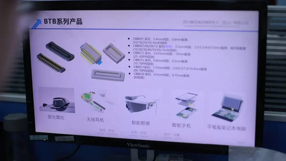
Nearby mezzanine interconnects still matter. Dense signal BTB inside the same module may use 0.4 mm pitch automotive board-to-board connectors or 0.5 mm pitch automotive board-to-board connectors. Catalog BTB orientation (per catalog): 0.4 mm themes list heights 1.5–4.0 mm, 30–70 pins, 0.3 A, −40 to 125°C; 0.5 mm lists heights 3.0–5.0 mm, 10–80 pins, 0.5 A per contact. Keep Ethernet and BTB as separate RFQ lines so SI owners and mechanical owners do not overwrite each other’s constraints.
Mechanical Survival And Float
An in-vehicle connector must hold electrical performance through vibration, thermal cycling across the listed temperature window, humidity, and the mating cycles expected in production, service, and rework. Look for robust locking, adequate contact normal force, and—where two rigid boards mate inside a module—floating structures that decouple PCB tolerance from the contact interface. Listed Ethernet-related parts note 0.35 mm float per catalog; for broader mezzanine float options see floating board-to-board connectors (catalog examples: CBB020 80 pin at 4.75 mm height; CBB023/024/025 with 3.0 A power pins and TC9-1000BASE listing per catalog—confirm float capability without inventing additional travel numbers).
What To Ask Your Supplier Before Freezing Copper
Mated-pair S-parameters for the data class frequency range
Temperature grade and vibration test conditions available for the PN
Plating specification and mating-cycle rating (catalog lists 10 cycles for the Ethernet-related series above—confirm PN)
Power-pin current if hybrids are used (5 A power pins listed per catalog on those transition parts)
Withstanding voltage evidence (500 V listed per catalog—confirm PN)
Whether customer documentation packs (PPAP-style / IMDS-style items) are available on request
Long-term supply communication habits suited to vehicle platforms
Drawing and report discipline is covered in what technical drawings and test data matter most before connector procurement. Sample and release gates remain essential: what buyers should check before approving connector samples and how to approve connector samples for mass production. Factory process context sits on manufacturing quality.
Design Guide Snapshot (Per Catalog)
| Item | Catalog orientation | Engineer action |
|---|---|---|
| COT001 pitch | 1.8/2.5 mm | Match adapter / board need |
| COT002 pitch | 2.54 mm | Confirm mating face |
| COT022 | 1.80/2.50 mm side entry | Check cable exit keep-out |
| Power pins | 5 A (listed) | Derate for temperature |
| Float | 0.35 mm (listed) | Review screw stack stress |
| Data listing | TC9 1000BASE-T1 (STP) | Request S-parameters |
| Cycles / temp / VW | 10 cycles; −40–125°C; 500 V | Confirm PN datasheet |
Engineer Checklist Before Layout Freeze
[ ] Data class and cable media (STP/UTP) stated
[ ] Candidate PN from Ethernet product page selected
[ ] Footprint and antipad rules reviewed with SI
[ ] Float / locking decision documented
[ ] Power-pin budget separated from BTB signal pins
[ ] S-parameter and environmental evidence requested
[ ] Sample class (design vs production-intent) defined
[ ] Parallel BTB / LVDS interfaces listed as separate lines
Display paths may still need LVDS connectors; treat them as parallel, not interchangeable with T1 Ethernet.
Bring SI, Mechanical, And Process Reviews To The Same Gate
Hold one cross-functional gate before Gerber release that records data class, media (STP/UTP), candidate PN, footprint rules, float/locking decision, and whether power pins on the Ethernet connector share current with other interconnects. Signal-integrity owners should sign the S-parameter request list; mechanical owners should sign keep-outs for side-entry parts such as COT022; process owners should confirm pick-and-place and reflow notes for the exact package.
After samples arrive, separate inspection disposition from pilot release. A connector can seat correctly and still fail channel masks once the cable, PCB stack-up, and ASIC package are combined. Plan a system-level link check on representative hardware before freezing dual-source options. Vehicle platforms outlive many consumer cycles, so also ask how the supplier communicates material or tooling changes that would force a footprint or plating revisit years into production.
FAQ
Can a generic high-speed digital connector replace an automotive Ethernet part?
Not safely. T1 budgets and vehicle mechanical stresses differ from generic digital mates. Validate the channel and the PN evidence.
How should designers use COT001 versus COT002?
Use pitch and mating style against the mechanical stack: COT001 lists 1.8/2.5 mm and COT002 lists 2.54 mm per catalog. Confirm side-entry needs with COT022 when cable exit direction binds.
Does 0.35 mm float remove alignment fixtures?
No. Listed float helps residual misalignment; fixtures and footprint control remain required.
What belongs in the first Ethernet RFQ?
Data class, media, target PN or competitor PN, stacking/side-entry notes, power-pin needs, documentation pack list, and volume band.
How do BTB and Ethernet coexist on one module?
Keep separate owners and RFQ lines. Ethernet owns the T1 channel; BTB owns mezzanine density and height—link both only for keep-out and ground strategy.
Request A Quote
Share data class, stacking or side-entry constraints, power-pin needs, and documentation expectations. Weicheng can propose connectors designed for automotive Ethernet applications with drawings and samples for engineering review. Contact https://www.wcjmconnect.com/contact.