
CBB099-XXSXX-XX Precision where boards meet.
Review CBB099-XXSXX-XX using the available catalog data, product view and reference drawings. Confirm the exact variant before design-in.
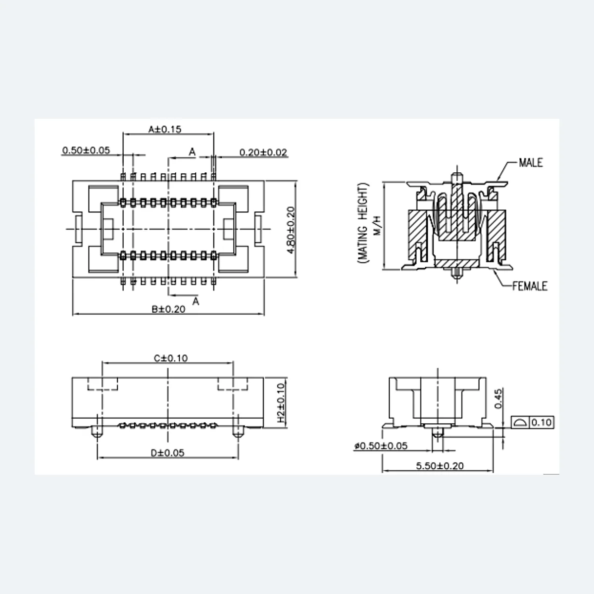
Every detail, in view.
Product geometry and related mating views. Confirm the exact variant before design-in.
Examine the connection.
Review the available product views and confirm this variant against the controlled drawing.
SELECT A VIEW BELOW
See the structure.
Review supplied product and engineering views. Confirm the exact variant against the current controlled drawing.
Check the
geometry.
Use this drawing as a reference for shape and orientation. Request the controlled drawing for the exact part before approving a PCB layout.
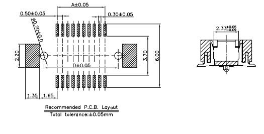 ENGINEERING VIEW
Two sides.
One system.
Review the mating counterpart, target stack height and assembly direction together.
Confirm the mating part.
The catalog lists CBB098. Confirm the exact variant, geometry and stack height with engineering.
About this model.
CBB099-XXSXX-XX is a board-to-board connector listed in the factory product catalog. Its recorded selection points include 0.5 mm pitch, 10–54 pins (even numbers; 2 × 5 to 2 × 27); 2 × n per drawing formula contacts, 2.0 mm with CBB098 mated height. The part number should be checked against the board or cable interface before any footprint is released.
The catalog lists Reflow (SMT) as the termination method. It names CBB098 as a mating part or series; engineering should confirm the precise counterpart and assembly height. Consider contact assignment, insertion direction, tooling access and the total tolerance stack in the completed product.
Use the specifications and drawings below as a traceable starting point for CBB099-XXSXX-XX. Values shown for a series are not a substitute for a released variant drawing. Request the latest datasheet, confirm any pending fields with engineering and validate the complete assembly under your own project conditions before production design-in.
Engineering, at a glance.
Catalog values below are tied to the product series or variant shown. Request the current controlled datasheet.
01 Mechanical
- Pitch
- 0.5 mm
- Termination
- Reflow (SMT)
- Insertion force
- 50gf/pin MAX
- Mating direction
- Straight mating
- Withdrawal force
- 3gf/pin MIN
- Contacts
- 10–54 pin (even numbers; 2 × 5 to 2 × 27); 2 × n per drawing formula
- Contact material
- Copper alloy
- Contact plating
- Contacts: gold or tin over nickel; A: gold flash. Pegs: tin over nickel.
- Mated height
- 2.0 mm with CBB098
02 Electrical
- Insulation resistance
- 100MΩ Min
- Rated current
- 0.5A
- Withstanding voltage
- 150V
- Contact resistance
- 50mΩ
- Rated voltage
- 50 V AC/DC
03 Environmental
- Operating temperature
- −25 ~ +85 ℃
- Salt spray
- 48H
- Mating cycles
- 30 cycles
04 Mating & assembly
- Mating part
- CBB098
05 Other catalog data
- Housing
- High-temperature plastic, UL94 V-0, black
Specifications source: factory catalog (PPT, slide 34) / drawing CBB099 rev B. Confirm current controlled documents before design release.
Choose the pin count. Check the geometry.
Dimensions are in mm, following the drawing columns. In formula rows, n is the number of contacts per row.
| PIN count | DIM A (mm) | DIM B (mm) | DIM C (mm) | DIM D (mm) |
|---|---|---|---|---|
| 10 | 2.0 | 7.0 | 4.0 | 4.5 |
| 12 | 2.5 | 7.5 | 4.5 | 5.0 |
| 14 | 3.0 | 8.0 | 5.0 | 5.5 |
| 16 | 3.5 | 8.5 | 5.5 | 6.0 |
| 18 | 4.0 | 9.0 | 6.0 | 6.5 |
| 20 | 4.5 | 9.5 | 6.5 | 7.0 |
| 22 | 5.0 | 10.0 | 7.0 | 7.5 |
| 24 | 5.5 | 10.5 | 7.5 | 8.0 |
| 26 | 6.0 | 11.0 | 8.0 | 8.5 |
| 28 | 6.5 | 11.5 | 8.5 | 9.0 |
| 30 | 7.0 | 12.0 | 9.0 | 9.5 |
| 32 | 7.5 | 12.5 | 9.5 | 10.0 |
| 34 | 8.0 | 13.0 | 10.0 | 10.5 |
| 36 | 8.5 | 13.5 | 10.5 | 11.0 |
| 38 | 9.0 | 14.0 | 11.0 | 11.5 |
| 40 | 9.5 | 14.5 | 11.5 | 12.0 |
| 42 | 10.0 | 15.0 | 12.0 | 12.5 |
| 44 | 10.5 | 15.5 | 12.5 | 13.0 |
| 46 | 11.0 | 16.0 | 13.0 | 13.5 |
| 48 | 11.5 | 16.5 | 13.5 | 14.0 |
| 50 | 12.0 | 17.0 | 14.0 | 14.5 |
| 52 | 12.5 | 17.5 | 14.5 | 15.0 |
| 54 | 13.0 | 18.0 | 15.0 | 15.5 |
| 2 × n | (n − 1) × 0.5 | 5.0 + (n − 1) × 0.5 | 2.0 + (n − 1) × 0.5 | 2.5 + (n − 1) × 0.5 |
Geometry made legible.
Select a view to open it at full size.
Dimension drawing
Technical view 2
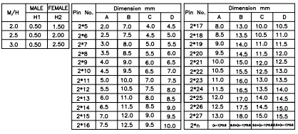
Reference drawing – request the controlled datasheet for design-in
A connector is a system.
Check both halves and the intended stack height before approving a footprint.
Explore assembly contexts.
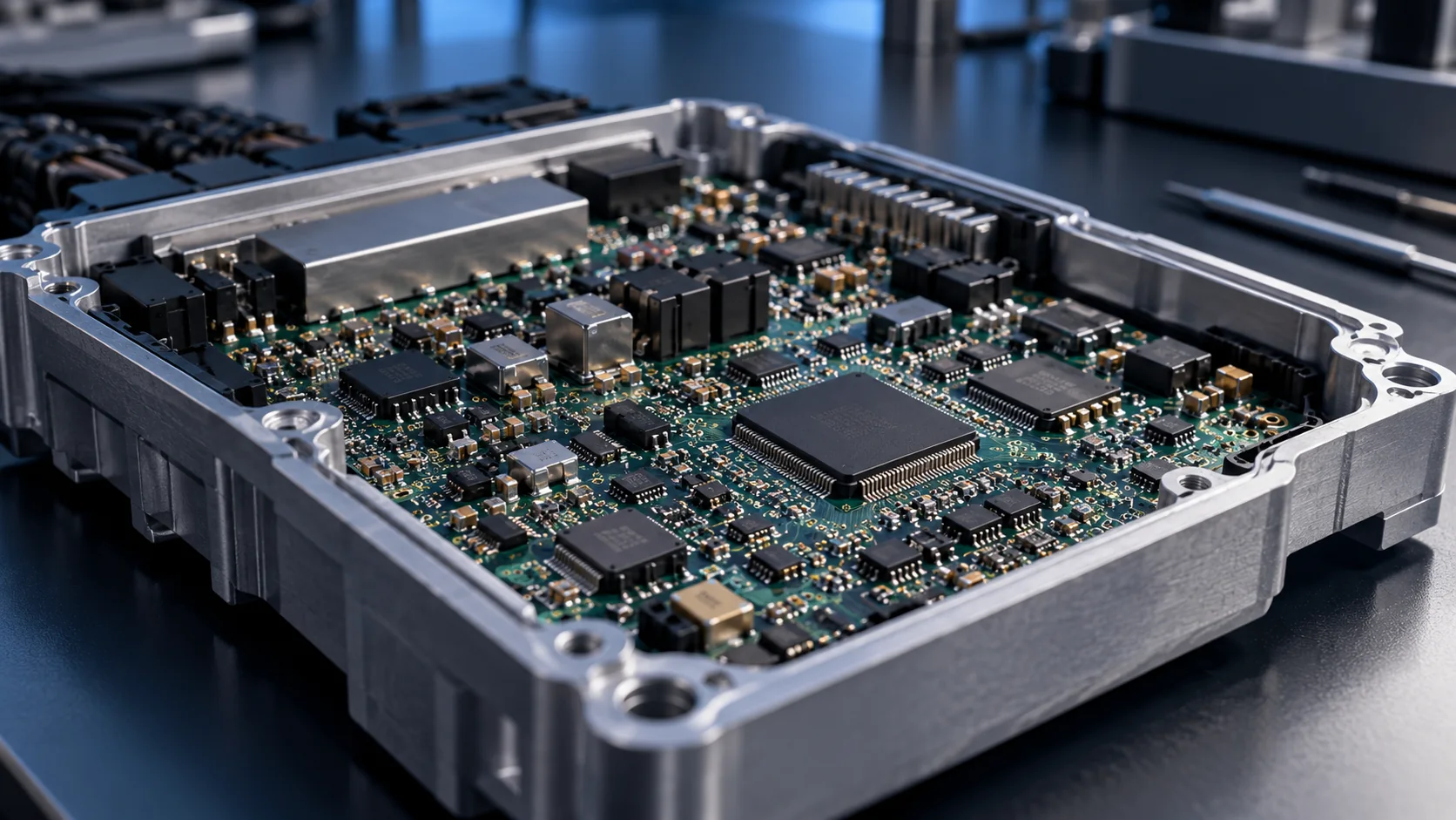
These guides explain system-level selection questions. The scenes are illustrations, not evidence that this exact model is qualified for an application.
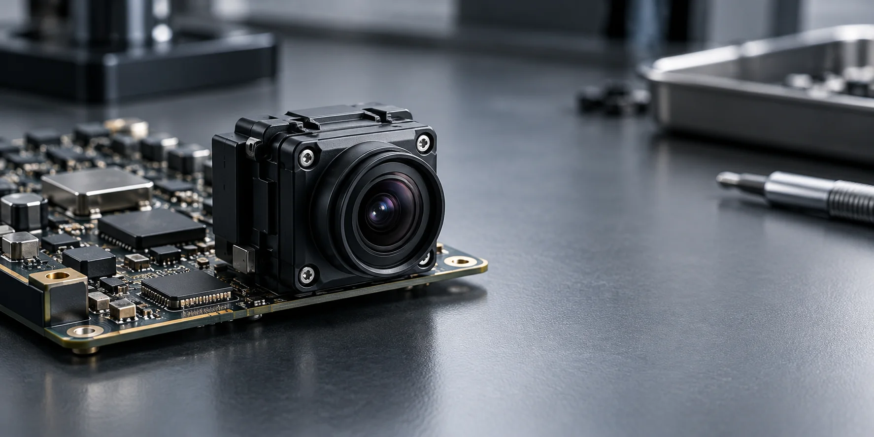 Illustration
Automotive cameras & ADAS sensors
Connector selection for compact camera and sensor boards designed for automotive applications.
 Illustration
Controllers & ECUs
Review stack height, retention and mating strategy for controller board assemblies.
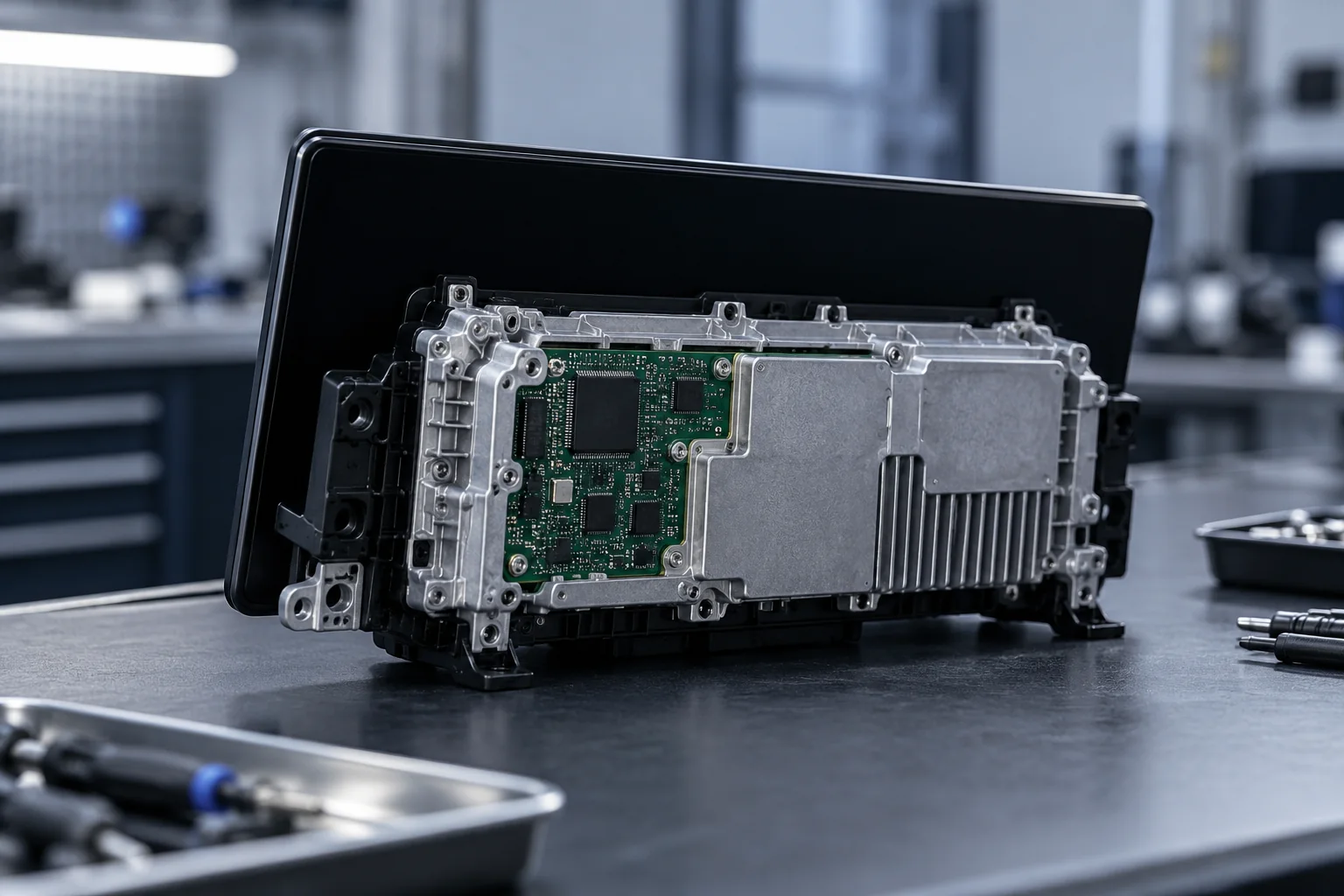 Illustration
Displays & infotainment
Board and signal interconnect planning for display modules and control electronics.
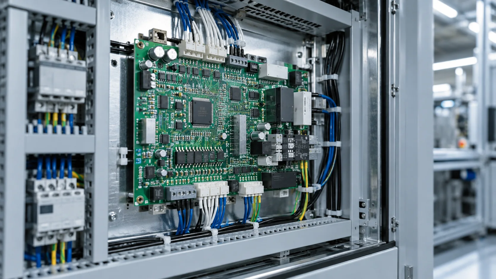 Illustration
Industrial control
Connector options for compact boards in industrial equipment.
Precision has a process.
Founded in 2021, Weicheng designs and develops molds, automation equipment and production lines in-house. Approximately 90% of production processes are fully automated.
Explore manufacturing →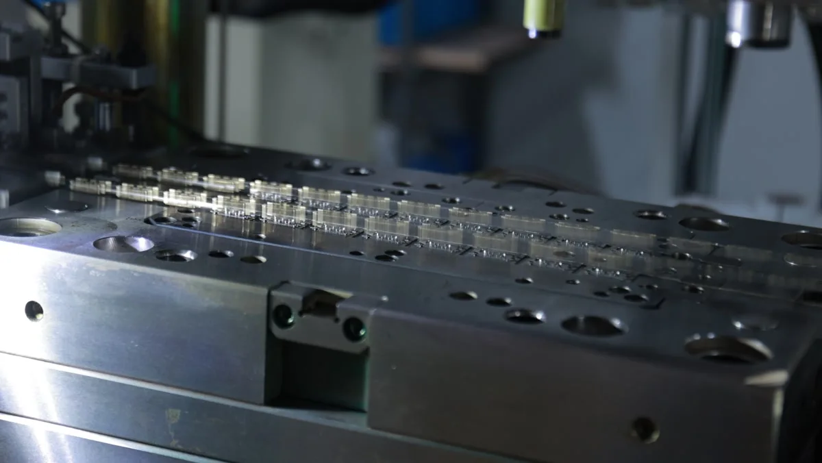 01 / PROCESSSTAMPING
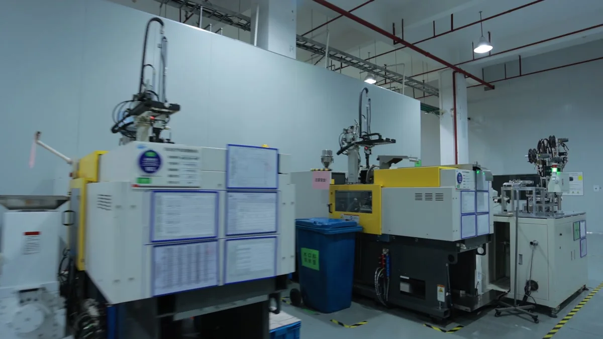 02 / PROCESSMOLDING
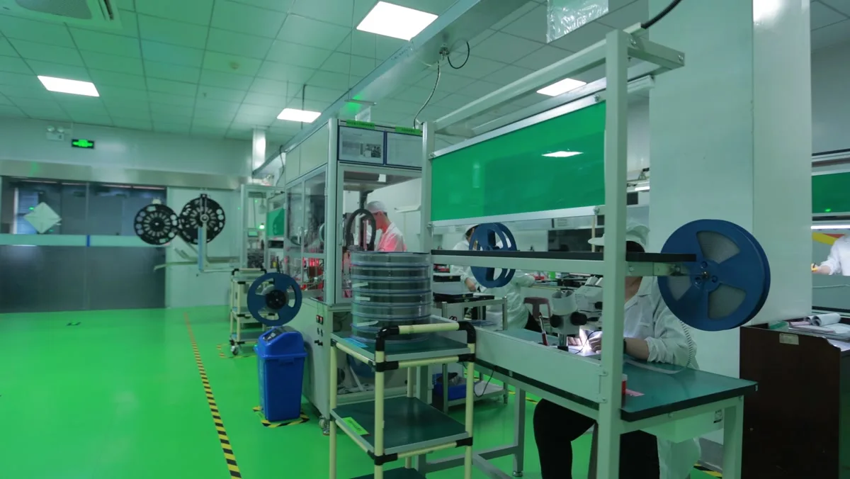 03 / PROCESSASSEMBLY
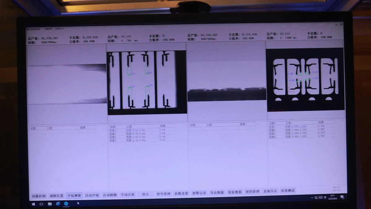 04 / PROCESSINSPECTION
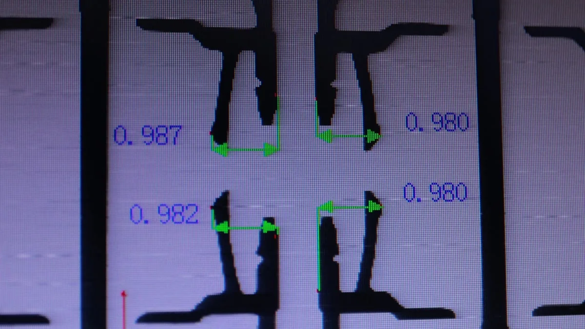 05 / PROCESSQUALITY
The files behind the design.
Request current controlled files for this exact model.
Datasheet
Current model specifications
2D drawing
Controlled dimensions and PCB layout
3D model
Mechanical integration file, if available
Good questions. Clear answers.
Where can I review dimensions for CBB099-XXSXX-XX?
The reference drawing and PIN × DIM table appear on this page. Request the controlled datasheet for design-in.
How do I check the mating part for CBB099-XXSXX-XX?
Review the listed mating series and confirm the exact variant and stack height with engineering.
Can I request files or samples for CBB099-XXSXX-XX?
Add the part number to the technical inquiry with your target contact count, quantity and project stage.
Tell us what you are building.
Share the part number, target quantity and project stage.