

Automotive cameras & ADAS sensors
Connector selection for compact camera and sensor boards designed for automotive applications.
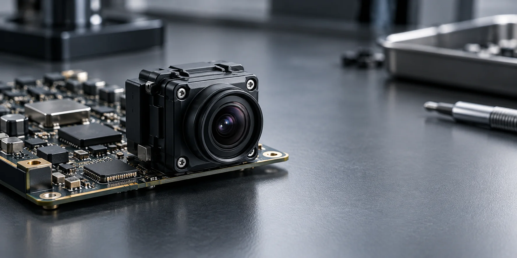
Define the interface first.
Confirm board space, pitch, mating direction, stack height, contact count and environmental conditions before choosing a connector. Current drawings and verified part-level specifications should be reviewed with engineering.
Explore product optionsQuestions for engineering.
What stack height and board layout must the connection fit?
Which circuits, current requirements and routing constraints apply?
Which tests and documentation must be provided for the intended use?
Series to review.
These series are candidates for evaluation, not a claim of qualification or fit for a particular assembly.
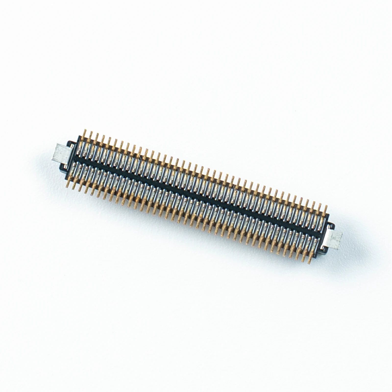 PRODUCT PHOTO
Board-to-Board
Compact plug and socket families across five pitch options.
Review series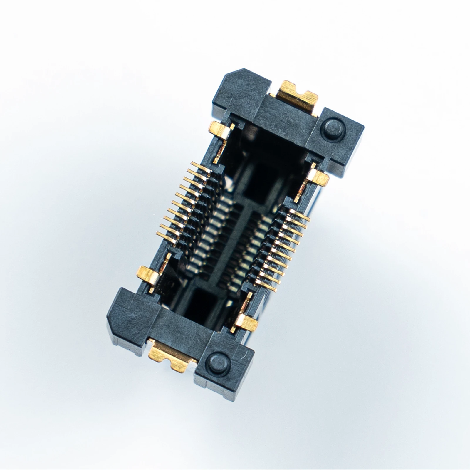 PRODUCT PHOTO
Floating Board-to-Board
Connector families with alignment tolerance for stacked boards.
Review series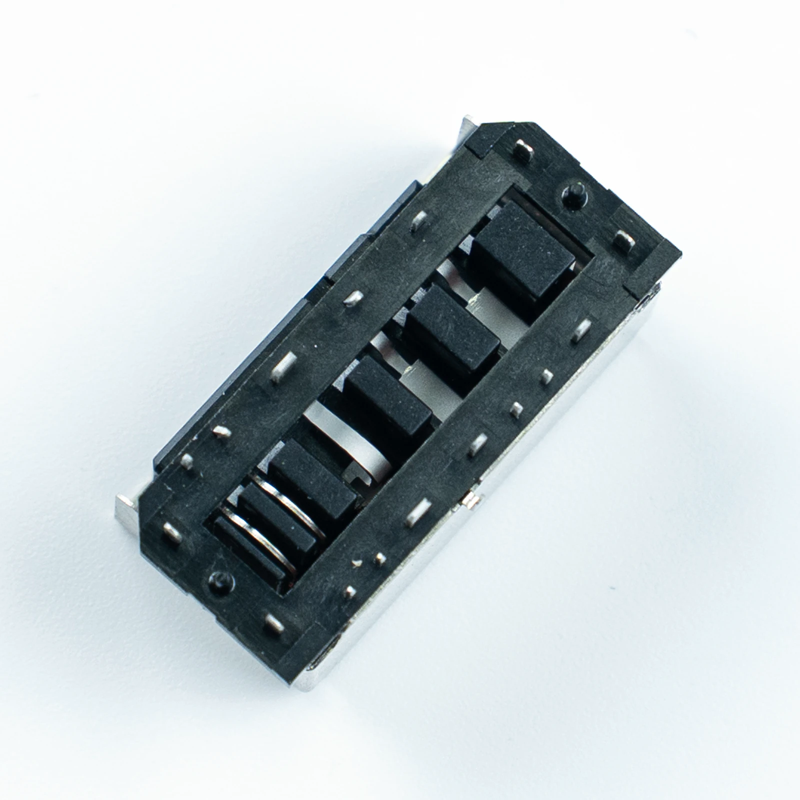 PRODUCT PHOTO
Floating Ethernet Adapter
Adapter connector families designed for in-vehicle electronics.
Review seriesStart with the physical interface
A compact camera or sensor assembly may combine a small PCB envelope with limited access during final assembly. Board spacing, cable route and enclosure sealing need to be defined before the connector candidate list is narrowed.
A connector is one part of a mechanical and electrical path. Start with a drawing that shows the boards, enclosure, cable or harness, insertion direction and service access. Identify which surfaces are fixed and where assembly variation can accumulate. The resulting design envelope gives engineering a useful way to compare connector families. Searching by a single nominal pitch too early can hide a better match for the real board spacing or assembly sequence.
For a board stack, review the board-to-board and floating families. For a signal path leaving the module, review the LVDS family as a possible starting point. These are selection routes, not a statement that a listed model is qualified for any vehicle program.
Record the target contact assignment before deciding on a part number. Note which circuits carry signals, power and ground; identify any need for shielding, controlled routing or a specific test method. The available contact count and mated height should be confirmed for the exact model, not inferred from another member of its family. Where a connector sits at a board edge or near a housing wall, check the orientation and the access required for both mating and inspection.
Candidate connector families
The linked families below provide starting points for an engineering comparison. The product data comes from the current factory catalog or a controlled model specification where stated. These links do not establish suitability for a complete device. The final choice depends on the application drawing, environmental requirements and validation evidence for the exact assembly. Share those requirements with the current part number when requesting technical files.
Board-to-Board
Compact plug and socket families across five pitch options.
Compare series →Floating Board-to-Board
Connector families with alignment tolerance for stacked boards.
Compare series →Floating Ethernet Adapter
Adapter connector families designed for in-vehicle electronics.
Compare series →| Model to inspect | Family | Sourced selection points |
|---|---|---|
| CBB001-xxPV2-xx | Board-to-Board | Pitch: 0.4 mm · Contacts: 10,16,24,30,34,40 pin |
| CBB001-xxSV2-xx | Board-to-Board | Pitch: 0.4 mm · Contacts: 10,16,24,30,34,40 pin |
| CBB063-XXSXX-XX | Board-to-Board | Pitch: 0.4 mm · Contacts: 10, 20, 30, 40, 50, 60, 70, 80, 90, 100, 120 |
| CBB066-XXSXX-XX | Board-to-Board | Pitch: 0.4 mm · Contacts: 10, 20, 30, 40, 50, 60, 70, 80, 90, 100, 120 |
| CBB069-XXPXX-XX | Board-to-Board | Pitch: 0.4 mm · Contacts: 10, 20, 30, 40, 50, 60, 70, 80, 90, 100, 120 |
| CBB096-XXPXX-XX | Board-to-Board | Pitch: 0.4 mm · Contacts: 10, 16, 20, 24, 30, 34, 40, 50, 60 pins |
| CBB097-XXSXX-XX | Board-to-Board | Pitch: 0.4 mm · Contacts: 24, 30, 34, 40, 50 pins |
| 10BBC050-H30-BPXXXXX | Board-to-Board | Pitch: 0.5 mm · Contacts: 10~80pin |
Review before design-in
For a board-to-board design, verify both halves of the mating pair and the resulting height. For a wire interface, verify the housing, terminal and board-side part as a system. For any signal-sensitive design, review the entire path through the PCB launch, contact interface and downstream route. A catalog entry is useful for shortlisting, but performance statements require a defined test condition and supporting data for the specific part and system.
Ask engineering for the current released drawing, revision identifier, sample availability and any relevant test report. Compare the report scope with the target product requirements; avoid assuming that a result for one series or environment transfers automatically to another. If a parameter is marked Pending confirmation, leave it out of the design approval basis until engineering supplies an authoritative value. Keep a record of the exact suffix and drawing revision used in the design file.
Selection checklist
- PCB outline and available stack height
- Assembly direction and allowable alignment variation
- Signal assignment and contact count
- Temperature and vibration requirements for the completed module
- Controlled drawing and test evidence needed for the target program
Use this checklist in a design review rather than as a pass or fail claim. A clear inquiry provides the PCB or harness geometry, intended mating method, candidate part number, estimated quantity and project stage. It also separates required values from preferences. That lets the connector team identify which questions can be answered from existing data and which need a fresh engineering review or a model-specific test.
After selecting a candidate, check the footprint at the exact ordering variant, inspect placement and solder access, and confirm that the mating operation works within the enclosure. A second review after prototype assembly can catch cable interference, board flex or contact access issues that are difficult to see in a schematic. Preserve the controlled drawing and test evidence in the project record so later procurement and production decisions use the same reference.