
To choose a board-to-board connector for reliable electronic assembly, match mechanical stack (mated height, orientation), pitch and pin count to the PCB layout, then confirm electrical ratings, materials/plating, and process fit for SMT or harness assembly. Selection that stops at “similar pitch” often causes mating issues, yield loss, or intermittent contact later. Treat the connector as part of the assembly system—boards, fixtures, reflow, and service plan—not as a standalone catalog pick.
Confirm Stack Geometry And Connection Style
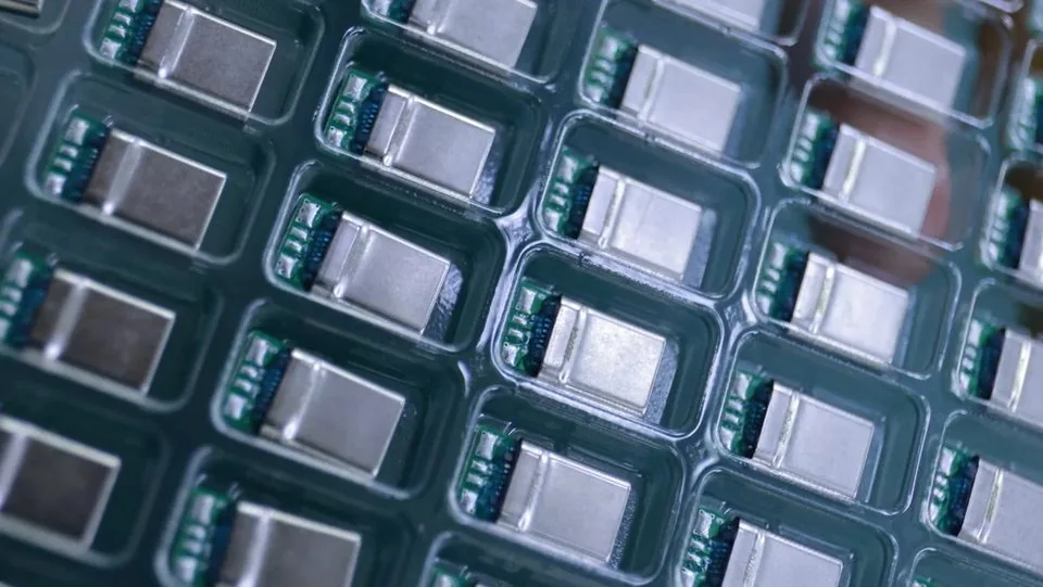
Start with the physical relationship between boards. Parallel board-to-board, mezzanine stacking, and right-angle or coplanar layouts impose different envelope and latch clearances. Record the required mated height from the mechanical stack, including component clearance under the plug/receptacle pair. Height errors are among the most expensive ECOs after copper is frozen.
Also define mating direction, keying, and whether operators or fixtures will engage the interface. Screwed assemblies and housing-guided modules often need more misalignment tolerance than a pure pick-and-place stack. When residual misalignment or vibration is expected, compare rigid families with floating board-to-board connectors during the same design review.
Pitch, Pin Count, And Density Versus Process Window
Pitch is the center-to-center contact spacing. Finer pitch increases density but narrows SMT and mating windows. Pin count must cover signal, ground, and any power budget without overcrowding pads.
Catalog-oriented orientation (per catalog; confirm the exact PN drawing):
0.4 mm BTB themes (CBB063/066/069 families): mated heights 1.5–4.0 mm, pin counts 30–70 (CBB066 50–70), 0.3 A per contact, operating range −40 to 125°C, high-speed listing pending validation — typical for smart watches, earphones, glasses, phones, tablets, and notebooks
0.5 mm BTB (CBB007 + receptacles): mated heights 3.0/3.5/4.0/5.0 mm, pin counts 10–80, 0.5 A per contact per catalog — commonly used for multi-board and general BTB electronics where a wider process window helps
For ultra-compact consumer stacks, review 0.4 mm pitch board-to-board connectors for consumer electronics. For modules designed for automotive applications or denser industrial boards that still need a practical assembly window, compare 0.5 mm pitch automotive board-to-board connectors and 0.4 mm pitch automotive board-to-board connectors.
Electrical And Mechanical Requirements
List electrical needs before shortlisting series: contact current (signal and any power pins), voltage, contact resistance stability, insulation resistance, and whether differential or high-speed paths need controlled impedance and ground strategy. Derate for ambient temperature and grouped power pins. Hybrid floating examples with dedicated 3.0 A power pins (CBB023/024/025 themes, per catalog) can keep fine-pitch signals while feeding local power—still confirm the exact datasheet.
Mechanical checks include insertion and withdrawal force, terminal retention, latch or friction lock behavior, and expected mating cycles. Field-serviceable interfaces need different durability evidence than one-time factory mates.
Materials, Plating, Packaging, And Process Fit
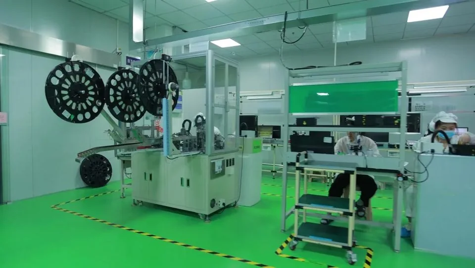
Copper-alloy terminals with gold or tin plating and high-temperature housings are typical building blocks; what matters for reliability is that plating callouts and housing grades match the approved revision. Packaging (reel, tray, pick-up cap) must fit automated placement. Review land pattern, stencil notes, and reflow compatibility with process engineering before Gerber release. Factory inspection and process control context is summarized on the manufacturing quality page.
Upstream buyers who want a broader selection frame can cross-check what buyers should check before choosing a high precision connector. Document readiness (outline, mating, PCB footprint) is covered in what technical drawings and test data matter most before connector procurement.
Assembly Reliability Checklist
| Decision item | Why it matters | Practical pass criteria |
|---|---|---|
| Mated height & orientation | Prevents stack clash | Matches mechanical CAD clearance |
| Pitch & pin count | Density vs yield | Fits layout and process capability |
| Current / signal plan | Power and SI budget | Ratings per catalog + derating noted |
| Plating & revision | Contact life | Drawing revision locked to sample |
| SMT / mating process | First-pass yield | Pad, stencil, fixture reviewed |
| Floating vs rigid | Misalignment / vibration | Decision documented in design review |
Practical Selection Flow
Freeze interface type (rigid BTB, floating BTB, or mixed with cable/LVDS).
Lock height, pitch preference, and pin map in writing.
Pull controlled drawings and STEP for candidate PNs.
Align electrical ratings and derating with the power/SI owner.
Run a process review (SMT or harness) before approving the footprint.
Plan sample inspection and production sign-off as separate gates.
Skipping step five is a common cause of “good sample, bad line yield.” Fine-pitch handling risks are expanded in common risks when sourcing fine-pitch or miniature connectors.
Align Stakeholders Before Freezing The Footprint
Connector selection fails quietly when mechanical, layout, process, and purchasing work from different assumptions. Hold a short cross-functional gate that records: approved stack height, pitch and pin map, plating preference, packaging method, and whether the interface is serviceable. Capture that gate in the same package used for RFQ and incoming inspection.
If the product mixes board-to-board signal paths with display or I/O cables, decide early whether LVDS or other cable connectors sit on the critical path. Mixed programs slip when BTB is frozen while cable length and locking are still open. Keep one interconnect owner accountable for clashes between shields, latches, and keep-outs.
When comparing series, prefer controlled drawings and STEP models over catalog photos. Photos hide coplanarity, keying depth, and pick-up-cap geometry. A one-millimeter seating error discovered after stencil design is far more expensive than an extra drawing review cycle.
FAQ
Is a smaller pitch always better for reliability?
No. Smaller pitch helps density but tightens assembly and mating windows. Choose the coarsest pitch that still meets space and pin-count needs.
How should buyers use catalog current ratings?
Treat values such as 0.3 A (listed 0.4 mm) or 0.5 A (listed 0.5 mm) as per-catalog orientation, then confirm the exact PN datasheet and apply temperature/grouping derating.
When is a floating connector preferred?
When board misalignment, housing screw stack-up, or vibration would stress solder joints on a rigid mate. Floating designs absorb residual movement; they do not replace proper footprint control.
What documents should accompany the first RFQ?
Target pitch/height/pin count, application environment, annual volume band, and controlled drawings or competitor PNs. Photos alone are not enough.
Do consumer and automotive-oriented selections follow the same steps?
The decision sequence is the same; stress profiles and documentation depth differ. Programs designed for automotive applications usually need tighter mapping of vibration, temperature, and evidence packages.
Request A Quote
Share stacking height, pitch preference, pin count, application environment, and process notes (SMT or harness). Weicheng can map requirements to suitable board-to-board series and supply drawings or samples for engineering review. Start an RFQ at https://www.wcjmconnect.com/contact.